
Automated apparatus and method for preparing contact lenses for inspection and packaging

a technology of automatic apparatus and contact lens, which is applied in the field of manufacturing ophthalmic lenses, can solve the problems of high production rate of contact lens handling and high availability of fully automated equipment, and achieve the effect of reducing the formation of air bubbles

Inactive Publication Date: 2001-11-06
JOHNSON & JOHNSON VISION CARE INC
View PDF9 Cites 15 Cited by
  • Summary
  • Abstract
  • Description
  • Claims
  • Application Information

AI Technical Summary

Benefits of technology

It is further an object of the present invention to provide an improved method of inspecting molded contact lenses wherein the lenses are inspected in deionized and degassed water to minimize the formation of air bubbles which would create false negative automatic lens inspection data.

Problems solved by technology

While U.S. Pat. Nos. 5,080,839 and 5,094,609 contemplate that the entire hydration process and transfer to final packaging may take place in a fully automated fashion, and while the chamber and process described in the foregoing patents enabled automated handling of the lens during hydration, suitable automated equipment to prepare the lenses for inspection and to handle the lenses at high production rates to implement the methods thereof in a fully automated apparatus was not readily available or taught by the prior art

Method used


Image

  • Automated apparatus and method for preparing contact lenses for inspection and packaging
  • Automated apparatus and method for preparing contact lenses for inspection and packaging
  • Automated apparatus and method for preparing contact lenses for inspection and packaging

Examples


Embodiment Construction

The present invention was designed for and is particularly adapted for use in the post hydration processing section of an automated contact lens production facility. Contact lenses molded in an automated production line, such as that described in co-pending application U.S. Ser. No. 08 / 258,654 entitled "Consolidated Contact Lens Molding"; hydrated in a hydration system as described in U.S. Ser. No. 08 / 258,556, now U.S. Pat. No. 5,476,111 entitled "Automated Method and Apparatus for Hydrating Soft Contact Lenses"; and automatically inspected as described in U.S. Ser. No. 07 / 993,756, now U.S. Ser. No. 08 / 598,068 entitled "Lens Inspection Method and Apparatus" are particularly benefited by the present invention.

Post Hydration Processing

The present invention envisions a multi-purpose disposable lens package carrier which transports a contact lens during inspection thereof, and serves as a portion of the final packaging after inspection.

A suitable package carrier 20 is illustrated in FIG...


PUM

PropertyMeasurementUnit
pressureaaaaaaaaaa
diameteraaaaaaaaaa
temperatureaaaaaaaaaa

Abstract

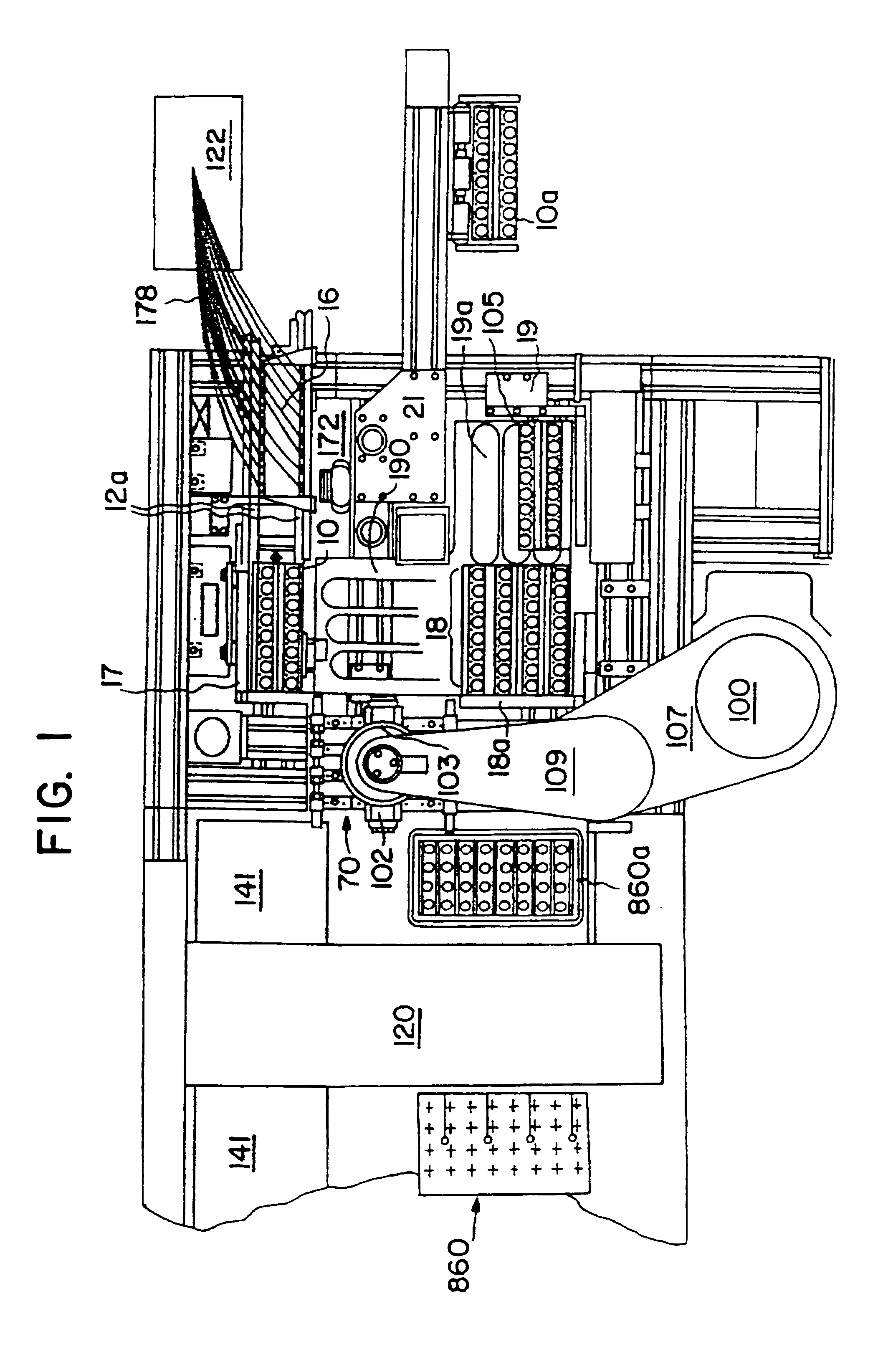
An apparatus is provided for removing and transporting articles, such as contact lens sections from a manufacturing line to inspection and packaging stations. The lenses are deposited in a transparent plastic primary package which carries the lenses through the inspection station and becomes part of the primary package when a cover is sealed thereto. The invention includes various assemblies, including lens transfer assemblies, deionized water filling and removal assemblies, a water degassing assembly, a lens inspection assembly, and a lens package sealing assembly. The lenses are removed from pallets at a post hydration station, transported and spatially redistributed, and deposited in the primary packages disposed on a second set of pallets. The packages on the second set of pallets are filled with degassed deionized water. The contact lenses and packages are then transported to an inspection station. After inspection, the lenses and packages are transported to a water removal assembly, and then to another transfer assembly. This transfer assembly separates those lenses which passed inspection from those which did not, and places those that did in a consolidating assembly. The lenses and packages are then filled with saline solution and a foil label is then sealed thereto to form the primary package.

Description

FIELD OF THE INVENTIONThe present invention relates generally to the field of manufacturing ophthalmic lenses, especially molded, hydrophilic contact lenses, and more specifically to an automated apparatus for handling and preparing contact lenses for inspection and packaging.DESCRIPTION OF THE PRIOR ARTThe molding of hydrophilic contact lenses is disclosed in U.S. Pat No. 4,495,313 to Larsen; U.S. Pat No. 4,640,489 to Larsen, et al.; U.S. Pat. No. 4,680,336 to Larsen et al.; U.S. Pat. No. 4,889,664 to Larsen et al.; and U.S. Pat. No. 5,039,459 to Larsen et al., all of which are assigned to the assignee of the present invention.These prior art references disclose a contact lens production process wherein each lens is formed by sandwiching a monomer or monomer mixture between a front curve (lower) mold section and back curve (upper) mold section, carried in a two by four mold array. The monomer is polymerized, thus forming a lens which is then removed from the mold sections and furth...

Claims


Application Information

Patent Timeline
Patent Type & Authority Patents(United States)
IPC IPC(8): B65B25/00B65B57/10B65B5/00B65B57/00B65B57/14B65B5/08G01M11/02B65B51/10B25J15/06B29C37/00B29D11/02G01M11/00B65B5/10B65B35/36B65B55/22G02C7/04
CPCB29D11/0024B29L2011/0041B65B5/08B65B5/10B65B25/008B65B35/36B65B55/22B65B57/10B65B57/14B65B2051/105G01M11/02G01M11/0207G01M11/0214Y10S134/901B29D11/00259
Inventor MARTIN, WALLACE ANTHONYEDWARDS, RUSSELL JAMESGUNDERSEN, BORGE PETERKEENE, DARREN SCOTTKINDT-LARSEN, TURELEPPER, JOHN MARKMADSEN, NIELS J.O SLASHED.RGENRAVN, THOMAS CHRISTIANWANG, DANIEL TSU-FANGHOLLEY, WILLIAM EDWARD
Owner JOHNSON & JOHNSON VISION CARE INC
Learn More