
Pilot resource allocation for a MIMO system

a pilot signal and resource allocation technology, applied in diversity/multi-antenna systems, transmission path sub-channel allocation, wireless communication, etc., can solve the problems of increasing pilot signalling time, affecting the transmission of payload data, so as to facilitate implementation and enhance reception sensitivity and quality

Inactive Publication Date: 2018-05-15
SONY CORP
View PDF12 Cites 0 Cited by
  • Summary
  • Abstract
  • Description
  • Claims
  • Application Information

AI Technical Summary

Benefits of technology

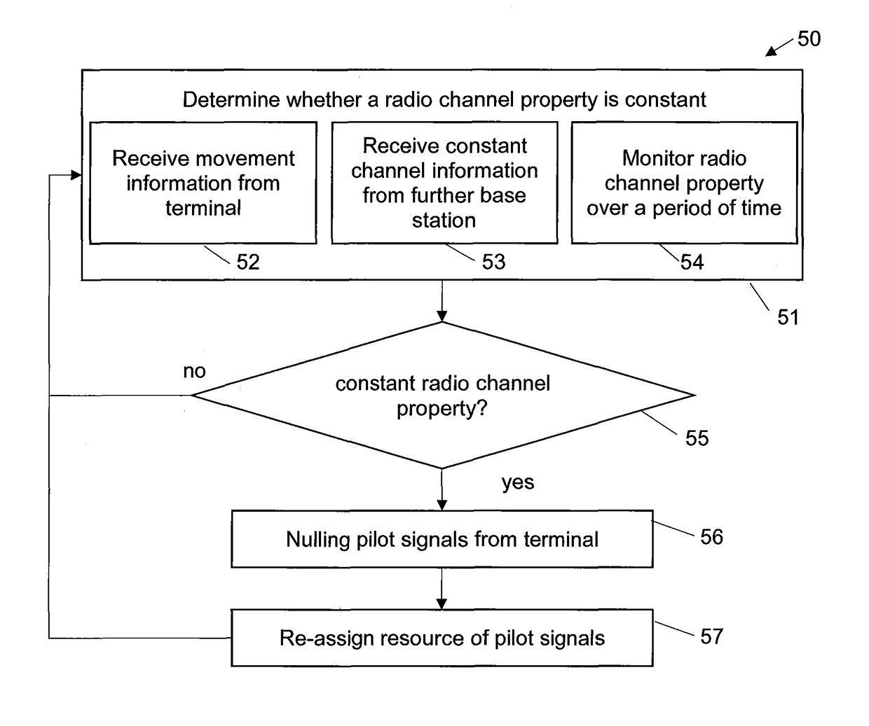
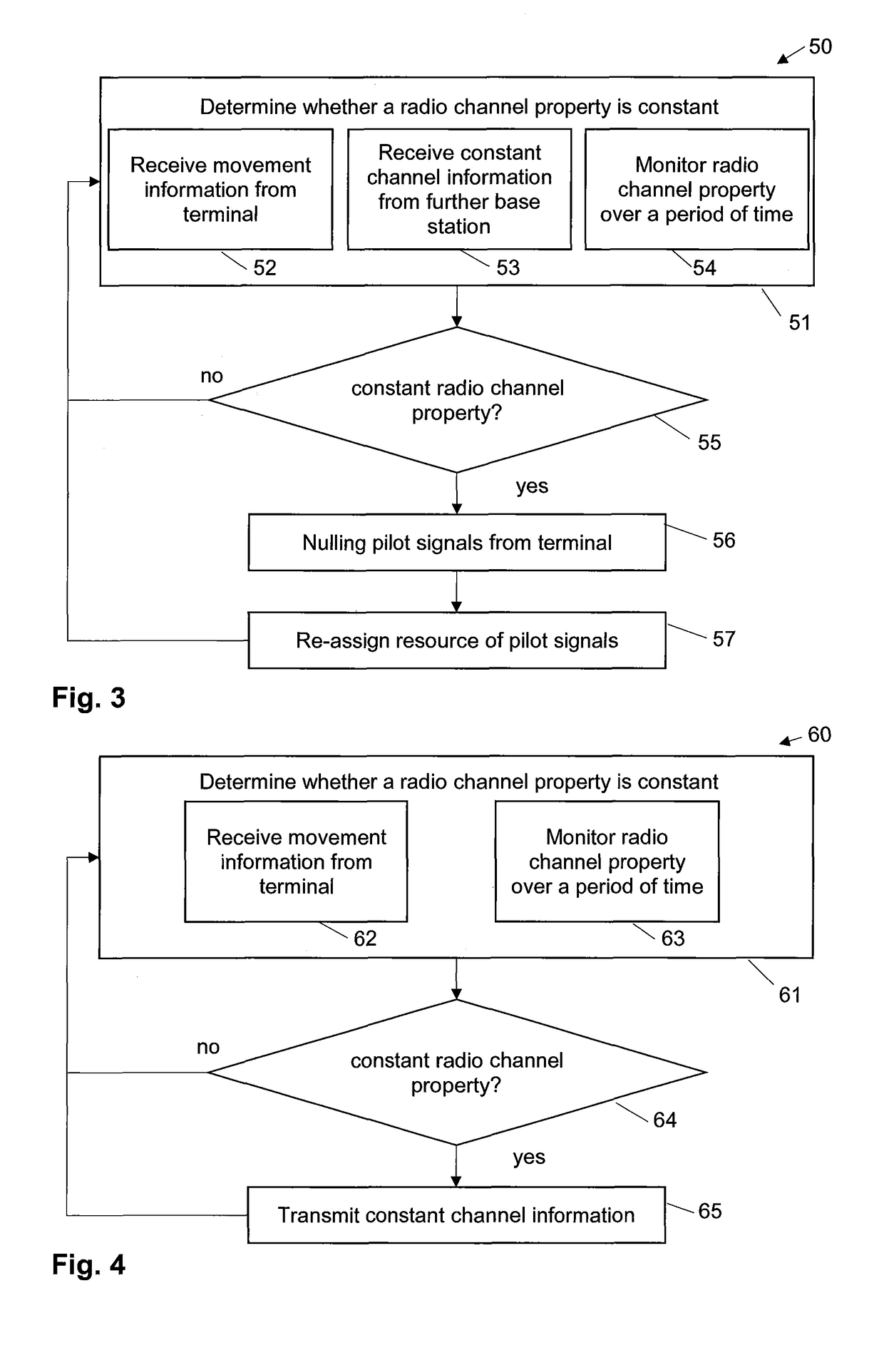
The patent text describes a method for a base station to determine if a pilot signal from a terminal is valid or not, and to use the same resource for another terminal if the pilot signal is not valid. This helps to improve the efficiency of resource allocation in a MIMO system. Additionally, the base station can also determine if the radio channel property between the terminal and the plurality of antennas is constant over a period of time, and use the same resource for another terminal if the radio channel property is constant. This further enhances the efficiency of resource allocation.

Problems solved by technology

For a large number of terminals, the time required for all terminals to transmit their pilot signals may exceed the available pilot signalling time in each frame.
While the pilot signalling time, i.e. the number of time slots allocated to the pilot signalling, may be adjusted dynamically, the transmission of payload data would be negatively effected if the pilot signalling time was increased too much.
Therefore, the resources for transmitting pilot signals are limited.
Furthermore, for mobility reasons, the validity of the channel as defined by the configuration parameters is limited.
Therefore, the transmission of pilot signals requires an considerable amount of resources.

Method used


Image

  • Pilot resource allocation for a MIMO system
  • Pilot resource allocation for a MIMO system
  • Pilot resource allocation for a MIMO system

Examples


Embodiment Construction

[0039]In the following, exemplary embodiments of the present invention will be described in more detail. It is to be understood that the features of the various exemplary embodiments described herein may be combined with each other unless specifically noted otherwise. Same reference signs in the various drawings refer to similar or identical components. Any coupling between components or devices shown in the figures may be a direct or indirect coupling unless specifically noted otherwise.

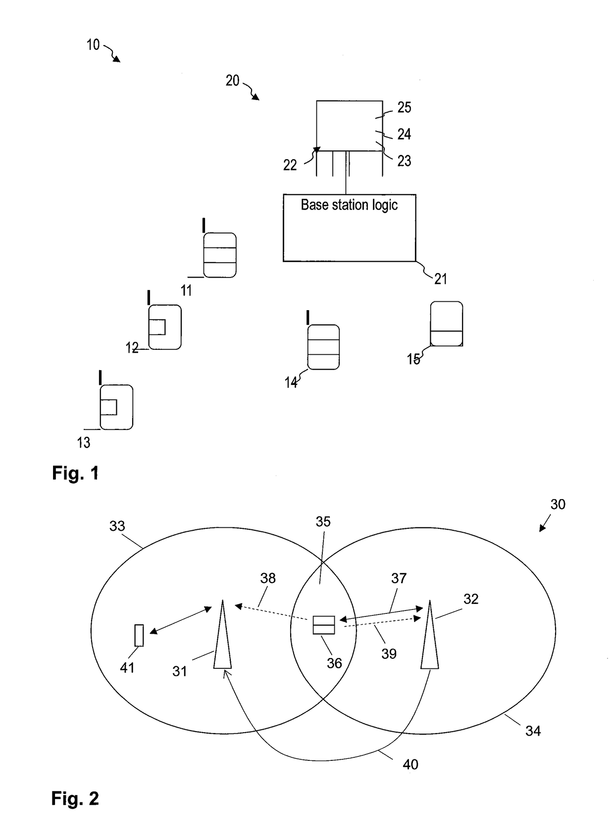
[0040]FIG. 1 shows a communication system 10 according to an embodiment. The communication system 10 is a multiple-input and multiple-output (MIMO) system and includes a MIMO base station 20 according to an embodiment. The MIMO communication system 10 may be a massive MIMO system (MaMi), and the MIMO base station may have a large number of antennas, for example several tens or in excess of one hundred antennas.

[0041]The base station 20 comprises a plurality of antennas 22. The antennas 23-25 may be ...


PUM


Abstract

The present application relates to a method of allocating resources for transmission of pilot signals of a plurality of terminals of a cellular multiple-input and multiple-output system. The cellular MIMO system comprises a base station having a plurality of antennas and a logic which analyzes pilot signals received from a terminal at the plurality of antennas to obtain information about a radio channel property of the radio channel between the terminal and the plurality of antennas. According to the method, the base station determines whether the radio channel property between the terminal and the plurality of antennas is constant over a period of time. If the radio channel property is constant over a period of time, receiving parameters of the plurality of antennas are configured for nulling pilot signals from the terminal, and a resource, which is assigned to the terminal for a transmission of pilot signals, is assigned to another terminal.

Description

FIELD OF THE INVENTION[0001]The present invention relates to cellular communication systems, in particular, to methods and devices for a resource allocation for a transmission of pilot signals in a cellular multiple-input and multiple-output (MIMO) system.BACKGROUND OF THE INVENTION[0002]Mobile data and voice communication continues to grow. The increasing popularity of data and voice communication requires that communication needs of a large number of users must be met which are all located within a small area, a case referred to as dense crowd scenario in the art. Typical examples include sports arenas, shopping malls or large office buildings.[0003]In order to increase data transmission performance and reliability, the so-called multiple-input and multiple-output (MIMO) technology may be used in a wireless radio telecommunication system for transmitting information between a base station and terminals of users.[0004]MIMO systems may use multiple send and receive antennas for wire...

Claims


Application Information

Patent Timeline
Patent Type & Authority Patents(United States)
IPC IPC(8): H04W72/04H04B7/00H04W4/02H04L5/00H04B7/04H04B7/0413H04W4/33
CPCH04W72/0453H04B7/00H04B7/0413H04L5/005H04W4/33H04W72/042H04W72/0413H04W4/027H04L5/00H04B7/0417H04B7/0452H04B7/06H04W72/21H04W72/23
Inventor BENGTSSON, ERIK
Owner SONY CORP
Learn More