Method for checking the function of a sensor for detecting particles, and a sensor for detecting particles

a technology for detecting particles and sensors, applied in the field of detecting particles, can solve the problems of not being able to distinguish whether the undershooting of the threshold value is due to aging, the self-diagnosis is resistant to aging only to a limited extent, and the sensor aging is generally associated with a drop in the self-diagnosis curren

Active Publication Date: 2018-05-08
ROBERT BOSCH GMBH
View PDF25 Cites 2 Cited by
  • Summary
  • Abstract
  • Description
  • Claims
  • Application Information

AI Technical Summary

Benefits of technology

[0008]Therefore, a method for checking the function of a sensor for detecting particles, in particular soot, and a sensor for detecting particles, in particular soot, are provided, which at least largely avoid the disadvantages of known methods and devices and in which, for example, shunts may be eliminated as offsets.
[0029]Thus, within the scope of the present invention, a change of the operating strategy and an adaptation of the software of the operating electronics of an internal combustion engine are provided, with which the lifetime of the electrode self-diagnostics may be improved significantly. In particular, by measuring the intrinsic conductivity of the electrode measurement cell twice at different temperatures and evaluating the difference, shunt offset currents may be eliminated and the evaluation limit may be reduced. In contrast to the related art described above, the difference between two current or voltage values will now be used as an evaluation criterion. By using a difference formation to be able to eliminate the shunts as offsets, the evaluation threshold for the functionality of the sensor may be significantly reduced, for example, to 0.25 μA. A sensor failure caused by aging of the sensors and a related reduction of the self-diagnosis current is thus delayed significantly.

Problems solved by technology

Thus, the above-described form of self-diagnosis is resistant to aging only to a limited extent.
However, the aging of the sensor is generally associated with a drop in the self-diagnosis current.
Thus, after a certain period of aging, it is no longer possible to differentiate whether the undershooting of the threshold value is caused by aging or by a defect.

Method used


Image

  • Method for checking the function of a sensor for detecting particles, and a sensor for detecting particles
  • Method for checking the function of a sensor for detecting particles, and a sensor for detecting particles

Examples


Embodiment Construction

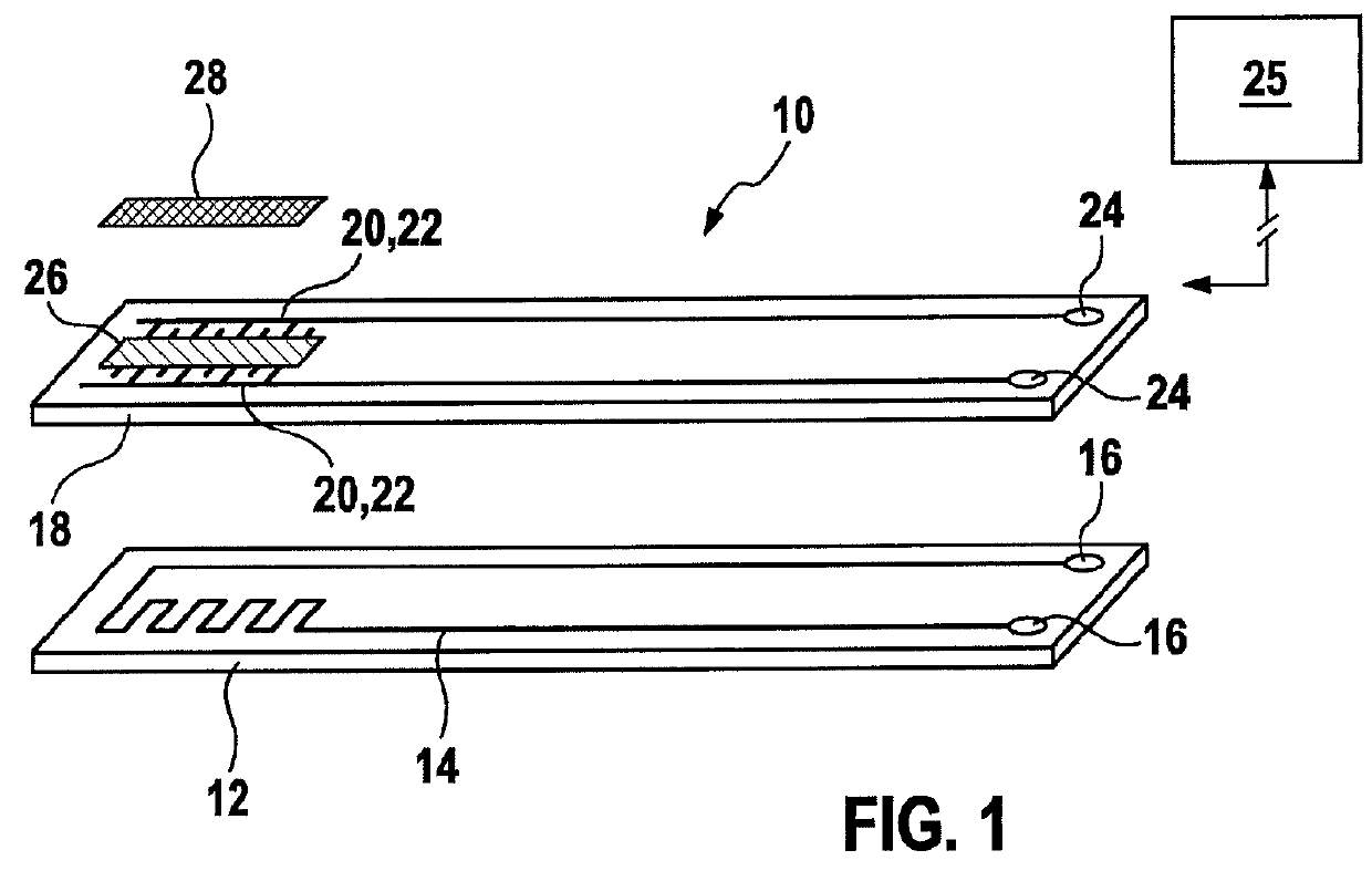
[0032]FIG. 1 shows a sensor 10 for detecting particles, in particular soot, in a gas flow, for example, an exhaust gas flow of an internal combustion engine, which is used for installation in an exhaust gas system of a motor vehicle. For example, sensor 10 is designed as a soot sensor and is preferably situated downstream from a soot filter of a motor vehicle having a diesel internal combustion engine.

[0033]Sensor 10 includes a plate-shaped carrier layer 12 which is at least partially manufactured from an electrically insulating material, for example, a ceramic such as aluminum oxide. A heating element 14 is integrated into carrier layer 12 which is connectable to a suitable voltage source via contacts 16 and is used to burn sensor 10 clean of possibly accumulated particles such as sooty particles.

[0034]A plate-shaped substrate 18 is situated on carrier layer 12 which is manufactured at least partially from an electrically insulating material, for example, a ceramic such as aluminum...


PUM

PropertyMeasurementUnit
temperatureaaaaaaaaaa
currentaaaaaaaaaa
temperatureaaaaaaaaaa

Abstract

A method for checking the function of a sensor for detecting soot is provided, the sensor including at least two measuring electrodes situated on a substrate made of an electrically insulating material, and a heating element, the method including: carrying out a first current-voltage measurement at a first temperature to ascertain a first measured variable, carrying out a second current-voltage measurement at a second temperature to ascertain a second measured variable, and forming a difference between the first measured variable and the second measured variable.

Description

BACKGROUND OF THE INVENTION[0001]1. Field of the Invention[0002]The present invention relates to sensors for detecting particles, in particular sooty particles in an exhaust gas flow of an internal combustion engine.[0003]2. Description of the Related Art[0004]It is known from practice to measure a concentration of particles in an exhaust gas, for example, sooty particles or dust particles, with the aid of two electrodes which are situated on a ceramic. This may, for example, be carried out via a measurement of the electrical resistance of the ceramic material separating the two electrodes. Such sensors are, for example, used in an exhaust gas system of an internal combustion engine, for example, an internal combustion engine of the diesel version. They are generally situated downstream from the internal combustion engine or the diesel particulate filter. Due to growing environmental awareness and partly due to legal requirements, soot emissions must be monitored in the future durin...

Claims


Application Information

Patent Timeline
Patent Type & Authority Patents(United States)
IPC IPC(8): F01N11/00G01M15/10G01N33/00G01N15/06G01R31/02G01N27/04F02D41/22F02D41/14F02D41/20
CPCG01N33/0006F02D41/1466F02D41/1494F02D41/222G01M15/102G01N15/0656G01N27/04G01R31/02G01N15/0606Y02T10/40F02D2041/2086G01R27/08
Inventor BESSEN, MICHAELHERWEG, KAROLAKLENK, MATHIASGAERTNER, BENJAMIN
Owner ROBERT BOSCH GMBH
Why Eureka
Try Eureka