Electronic device

Active Publication Date: 2018-04-24
ACER INC
View PDF41 Cites 1 Cited by
  • Summary
  • Abstract
  • Description
  • Claims
  • Application Information

AI Technical Summary

Benefits of technology

The invention is designed to solve issues of short circuit and poor heat dissipation in electronic devices. It achieves this by using a shunt design on the circuit board and larger layout space for the system positive and negative lines on the connector. Additionally, the system detection line prevents sparks and allows for the detection of signals actively. This design reduces manufacturing costs, simplifies structure, increases strength, and allows for a high power of 500 watts or more. The electronic device is also electrically connected to a power connector of the power supply device by only one system connector.

Problems solved by technology

However, since a user must insert two DC-in plugs simultaneously in order to attain the highest performance, if the user only inserts the first DC-in plug and forgets to insert the second DC-in plug, the performance of the electronic device then becomes halved.
Furthermore, since two DC-in jacks need to be set up, structure becomes more complicated, mold making becomes more difficult, and problems such as a greater loss of process tolerance, higher manufacturing costs and decreased structural strength will easily ensue.
However, in the above design, the system positive lines and the system negative lines are limited by the size of the circuit board so that the signal lines cannot be shunted from each another.
Therefore, not only is it easy to result in a short circuit and generate sparks and thus lead to safety concerns, but high density of the components disposed on the circuit board also causes problems of poor heat dissipation.

Method used


Image

  • Electronic device
  • Electronic device
  • Electronic device

Examples


Embodiment Construction

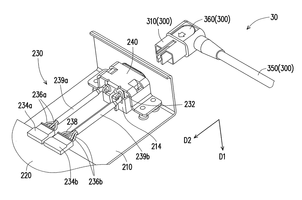
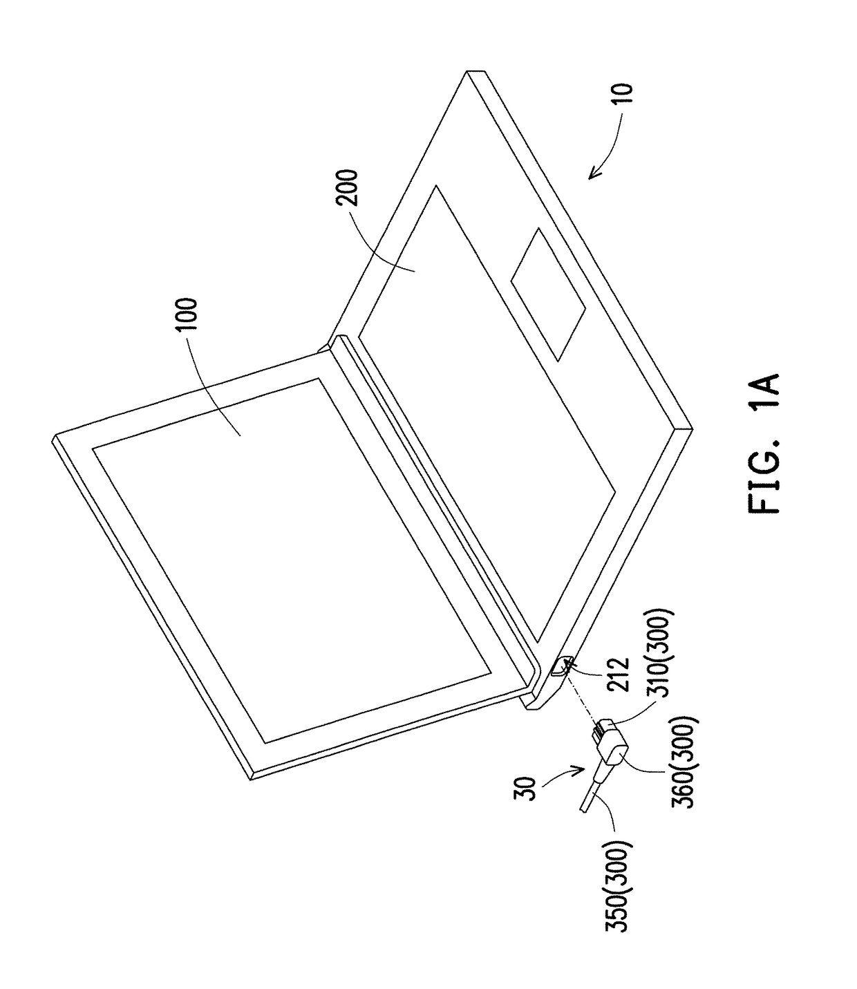
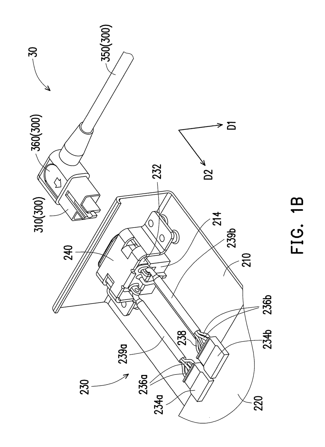
[0027]FIG. 1A illustrates a schematic view of an electronic device according to an embodiment of the invention. FIG. 1B illustrates a partially enlarged schematic view of the power supply device and the base unit of FIG. 1A. FIG. 1C illustrates a schematic view of the power supply device and the base unit of FIG. 1B from another perspective. FIG. 2 illustrates a schematic view of the system connector of FIG. 1A. FIG. 3 illustrates an enlarged schematic view of the fixing base of the casing and the system input terminal of the system connector of FIG. 1A. FIG. 4 illustrates a schematic view of the power connector of FIG. 1A. FIG. 5A and FIG. 5B illustrate the power connector of FIG. 1A from different perspectives respectively. FIG. 5C and FIG. 5D illustrate the system connector of FIG. 1A from different perspectives respectively.

[0028]First, with reference to FIG. 1A, FIG. 1B, FIG. 1C and FIG. 2 simultaneously, in this embodiment, an electronic device 10 is adapted to be electrically...


PUM


Abstract

An electronic device includes a display device and a base unit including a casing, a circuit board and a system connector. The system connector includes a system input terminal, a system positive terminal, a system negative terminal, system positive lines, system negative lines and a system detection line. The system input terminal is disposed corresponding to an opening of the casing, and the system positive terminal and the system negative terminal are electrically connected to the circuit board. The system positive lines are connected between the system input terminal and the system positive terminal, and the system negative lines and the system detection line are connected between the system input terminal and the system negative terminal. The system input terminal, the system positive terminal and the system negative terminal are non-overlapping in their orthographic projections on the casing.

Description

CROSS-REFERENCE TO RELATED APPLICATION[0001]This application claims the priority benefit of Taiwan application serial no. 106100803, filed on Jan. 11, 2017. The entirety of the above-mentioned patent application is hereby incorporated by reference herein and made a part of this specification.BACKGROUND OF THE INVENTIONField of the Invention[0002]The invention relates to an electronic device and particularly relates to an electronic device that has greater safety.Description of Related Art[0003]Currently, the power source of a laptop computer is mostly provided by an external power supply device, and a DC-in jack of a laptop computer receives power of approximately 360 watts only. In order to achieve high power, the laptop computer is usually provided with two DC-in jacks therein, so that the electronic device can achieve a high power of 500 watts or more. However, since a user must insert two DC-in plugs simultaneously in order to attain the highest performance, if the user only ins...

Claims


Application Information

Patent Timeline
IPC IPC(8): H05K5/00H01R13/44H01R13/64G06F1/26H01R12/53H01R24/50G06F1/16H01R103/00
CPCG06F1/26H01R13/44H01R12/53H01R24/50H01R13/64H01R2201/06G06F1/1616H01R2103/00H01R13/7137H01R24/28H01R24/76
Inventor WANG, YU-SHIHLIU, CHIH-CHUN
Owner ACER INC
Why Eureka
Try Eureka