Efficient dust-removing and heat-dissipating device in computer host

A heat dissipation device and computer technology, applied in the field of computers, can solve problems such as uneven heat dissipation, poor heat dissipation effect, and shortened lifespan, and achieve good heat dissipation effect, good user experience, and uniform heat dissipation

Inactive Publication Date: 2021-02-05
练月梅
View PDF0 Cites 0 Cited by
  • Summary
  • Abstract
  • Description
  • Claims
  • Application Information

AI Technical Summary

Problems solved by technology

These components will release heat when the computer is running. If it is not cooled, it will shorten its life and affect the experience of the computer, and after a period of time, it will have to be dust-removed. The current computer host does not have a dust-removal device. After using it for a period of time, the staff needs to disassemble it to remove dust from its internal parts, and the heat dissipation mechanism inside the current computer mainframe is fixed heat dissipation, which makes its heat dissipation uneven and the heat dissipation effect is not good.

Method used


Image

  • Efficient dust-removing and heat-dissipating device in computer host
  • Efficient dust-removing and heat-dissipating device in computer host
  • Efficient dust-removing and heat-dissipating device in computer host

Examples


Embodiment 1

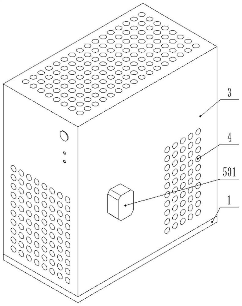
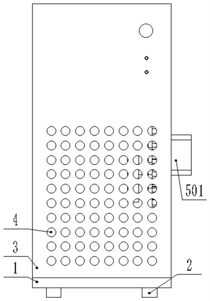
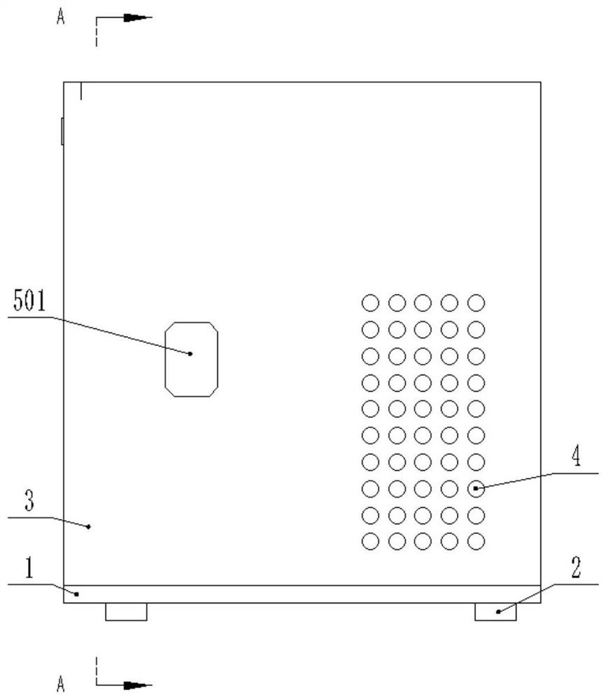
[0024] Example 1: Please refer to Figure 1-5 , a high-efficiency dust-removing and heat-dissipating device inside a computer mainframe, comprising a base 1, a cushion block 2 is fixedly connected to the bottom of the base 1, front, rear, left, and right, and a box body 3 is fixedly connected to the top of the base 1, and the surface of the box body 3 is provided with Cooling hole 4;

[0025] The front end of the outer middle part of the right wall of the box body 3 is fixedly connected with the driving mechanism 5. When in use, the driving motor 501 and the rotating motor 802 are turned on, and the output end of the driving motor 501 rotates to drive the rotation of the motor rotating shaft 502, thereby making the rotating plate 503 surround the motor rotating shaft 502 rotates, and then drives the driven gear 903 to rotate around the motor shaft 502 while rotating, and then makes the rotating gear 702 meshed with the transmission gear 701 rotate around the motor shaft 502 wh...

Embodiment 2

[0037] Embodiment 2: This embodiment is a further improvement of the previous embodiment: the material of the dust removal plate 704 is activated carbon.

[0038] The working principle of the present invention is: when in use, the driving motor 501 and the rotating motor 802 are turned on, the output end of the driving motor 501 rotates and then drives the rotation of the motor shaft 502, and then the rotation plate 503 rotates around the motor shaft 502, and then drives the driven gear 903 Rotate around the motor rotating shaft 502 while rotating, and then make the rotating gear 702 meshed with the transmission gear 701 rotate around the motor rotating shaft 502 while rotating, and then drive the rotating rod 703 to rotate, and then make the dust removal plate 704 fixedly connected with it to rotate automatically Rotate around the motor shaft 502 at the same time, and then remove the dust inside the box body 3; the output end of the rotating motor 802 rotates and then drives t...


PUM


Abstract

The invention discloses an efficient dust-removing and heat-dissipating device in a computer host, and relates to the field of computers. The efficient dust-removing and heat-dissipating device comprises a base, cushion blocks are fixedly connected below the base in a front-back and left-right symmetrical mode, a box body is fixedly connected above the base, and heat dissipation holes are formed in the surface of the box body; the front end of the middle of the outer side of the right wall of the box body is fixedly connected with a driving mechanism, the driving mechanism is rotationally connected with a fixing mechanism fixedly connected with the inner side of the right wall of the box body, and the fixing mechanism is engaged with a dust removal mechanism. A rotating mechanism is fixedly connected to the upper portion of the rear side of the middle of the inner side of the right wall of the box body and engaged with a transmission mechanism, and the transmission mechanism is slidably connected with a heat dissipation mechanism. The device not only can remove dust in the box body, but also is uniform in heat dissipation, good in heat dissipation effect and good in use experiencedue to the fact that the heat dissipation fan dissipates heat movably.

Description

technical field [0001] The invention relates to the field of computers, in particular to a high-efficiency dust removal and heat dissipation device inside a computer mainframe. Background technique [0002] The computer host refers to the container (Mainframe) used to place the motherboard and other major components in the computer hardware system. Usually includes CPU, memory, hard disk, optical drive, power supply, and other input and output controllers and interfaces, such as USB controllers, graphics cards, network cards, sound cards, and so on. These components will release heat when the computer is running. If it is not cooled, it will shorten its life and affect the experience of the computer, and after a period of time, it will have to be dust-removed. The current computer host does not have a dust-removal device. Also need the staff to disassemble it to remove dust to its internal parts after using for a period of time, and the heat dissipation mechanism inside the...

Claims


Application Information

Patent Timeline
Patent Type & Authority Applications(China)
IPC IPC(8): G06F1/18G06F1/20
CPCG06F1/183G06F1/20
Inventor 练月梅
Owner 练月梅
Why Eureka
Try Eureka