
Baggage conveyance tray

a conveyancing tray and baggage technology, applied in the direction of conveyors, transportation and packaging, tray containers, etc., can solve the problems that the effect of suppressing the placed baggage from sliding back and forth in the conveyance direction can be hardly expected, and achieve the effect of improving reducing the speed of the conveyancing, and increasing the conveyancing speed of the conveyor

Active Publication Date: 2018-04-24
DAIFUKU CO LTD
View PDF23 Cites 8 Cited by
  • Summary
  • Abstract
  • Description
  • Claims
  • Application Information

AI Technical Summary

Benefits of technology

[0003]However, the baggage conveyance tray described in Patent Literature 1 has a structure that two pieces of flat plates are connected in an obtuse V shape along the length direction in order for the baggage placement surface between the front and rear both raised wall plate portions to have the central portion in the right-left width direction being lowered and the right and left both sides being raised. The surface with which the baggage comes in contact is flat. Thus, the effect of suppressing the placed baggage from sliding back and forth in the conveyance direction can be hardly expected. Accordingly, it is conceivable when attempting to increase the conveyance speed of the conveyor to improve the conveyance efficiency that the baggage may widely slide back and forth in the conveyance direction due to inertia at the time of acceleration and deceleration and run into, and in some cases jump over, the front and rear raised wall plate portions. Therefore, the conveyance speed of the conveyor needs to be kept reduced such that the baggage or tray can be conveyed safely while prevented from being damaged.

Problems solved by technology

Thus, the effect of suppressing the placed baggage from sliding back and forth in the conveyance direction can be hardly expected.

Method used


Image

  • Baggage conveyance tray
  • Baggage conveyance tray
  • Baggage conveyance tray

Examples


Embodiment Construction

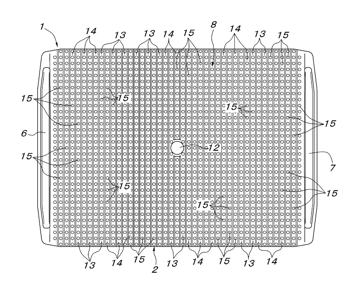
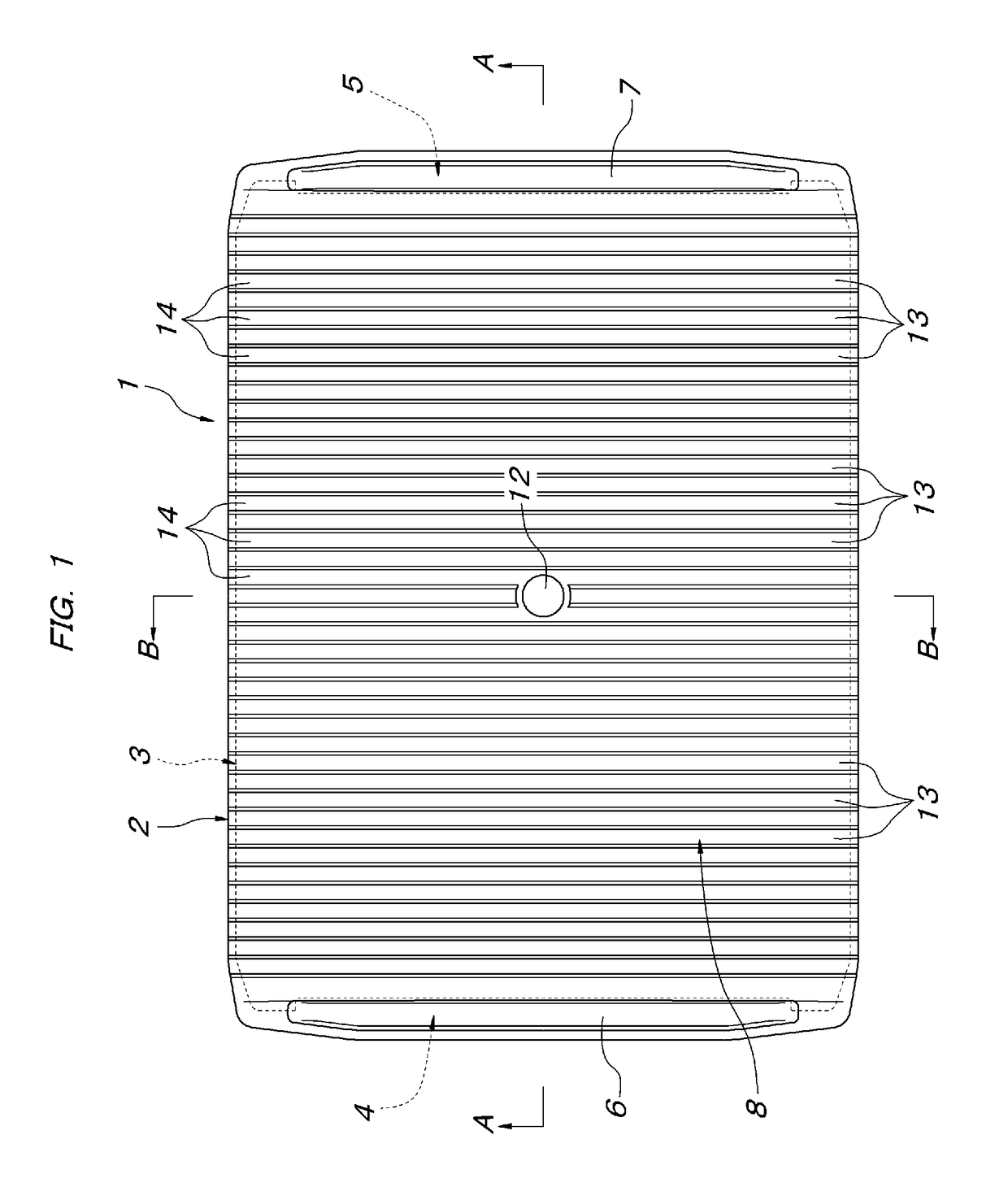
[0019]A tray 1 according to one embodiment of the present invention shown in FIGS. 1 to 3B has a solid structure integrally molded with expanded polypropylene (EPP), and a planar shape thereof is a rectangular shape (a rectangle) in which the front-rear length direction, which is the conveyance direction, is longer than the width in the right-left direction. Four corners in the planar shape are obliquely cut off and formed to have an obtuse angle. As shown in FIGS. 2A-2B and FIGS. 3A-3B, this tray 1 includes an upper tray main body 2 and a lower base portion 3 with the entire periphery one size smaller than the tray main body 2. Thus, both end portions in the front-rear length direction of the upper tray main body 2 are projected with respect to both end portions in the front-rear length direction of the lower base portion 3. Lower sides of the both end portions in the front-rear length direction of the upper tray main body 2 constitute recessed step portions 4, 5. The lower base po...


PUM

PropertyMeasurementUnit
lengthaaaaaaaaaa
heightaaaaaaaaaa
timeaaaaaaaaaa

Abstract

A baggage conveyance tray suitable for a sorting conveyor system for conveying baggage at airports has raised wall plate portions protruding on the front and rear both end portions of the tray in the length (conveyance) direction thereof extending in the right-left width direction of the tray. A baggage placement surface located between the front and rear both raised wall plate portions is concave along the length direction such that the central portion in the right-left width direction is lowered while the right and left both sides are raised. Elongated protrusion portions extending along the right-left width direction of the tray are disposed on the baggage placement surface at intervals in the length direction of the tray.

Description

FIELD OF THE INVENTION[0001]The present invention relates to a baggage conveyance tray used in a sorting conveyor system for conveying baggage, for example, at airports.BACKGROUND OF THE INVENTION[0002]As described in U.S. Pat. No. 6,471,039 (Patent Literature 1), this kind of baggage conveyance tray is used for safely conveying and sorting a variety of baggage different in shape, size, weight, etc., on a sorting conveyor. This tray is provided with raised wall plate portions protruding along the right-left width direction at front and rear both end portions of the tray of a rectangular shape whose length in the front-rear direction, which is the conveyance direction, is longer than the width in the right-left direction. A baggage placement surface between the front and rear both raised wall plate portions is concave along the length direction such that a central portion in the right-left width direction is lowered and right and left both sides are raised. That is, in the sorting co...

Claims


Application Information

Patent Timeline
Patent Type & Authority Patents(United States)
IPC IPC(8): A47F3/14B65D69/00B65D71/00B64F1/36B65D19/00B65D1/34B65D21/02
CPCB65D1/34B64F1/368B65D21/0212B65G2203/0216B65D2203/10B65G2201/0258
Inventor FUJIO, YOSHIHIKOISOMURA, TAKUYA
Owner DAIFUKU CO LTD
Learn More