Manifold pressure and air charge model

a manifold pressure and air charge technology, applied in the direction of electric control, machine/engine, fuel injection control, etc., can solve the problem of difficult direct measurement of the map

Active Publication Date: 2018-04-17
TULA TECH INC
View PDF55 Cites 31 Cited by
  • Summary
  • Abstract
  • Description
  • Claims
  • Application Information

AI Technical Summary

Problems solved by technology

This type of engine control may result in a complex and rapidly varying pressure waves forming in the intake manifold as a result of the irregular opening and closing of the intake valves, which makes direct measurement of the MAP extremely difficult.

Method used


Image

  • Manifold pressure and air charge model
  • Manifold pressure and air charge model
  • Manifold pressure and air charge model

Examples


Embodiment Construction

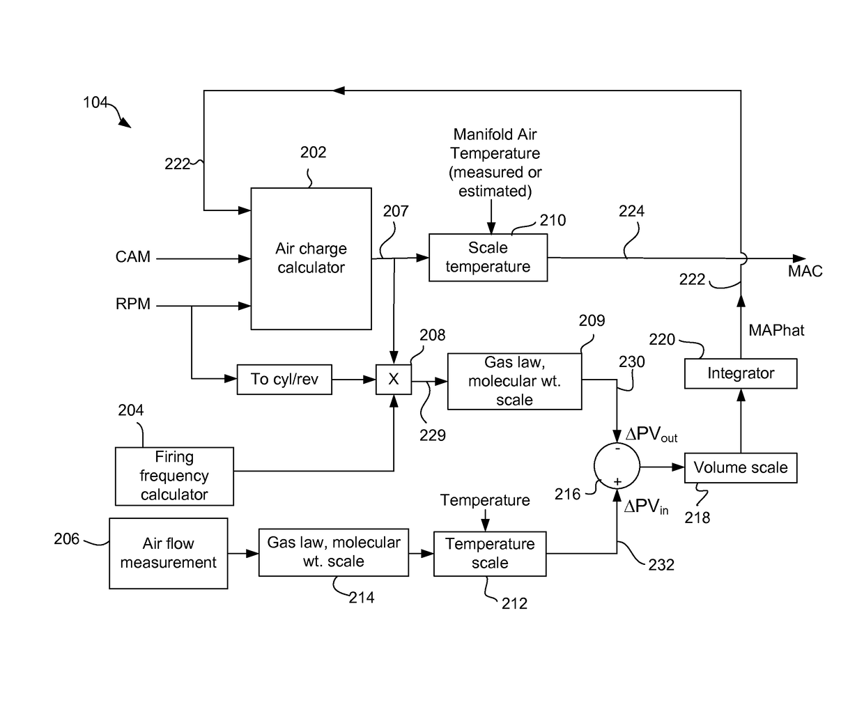
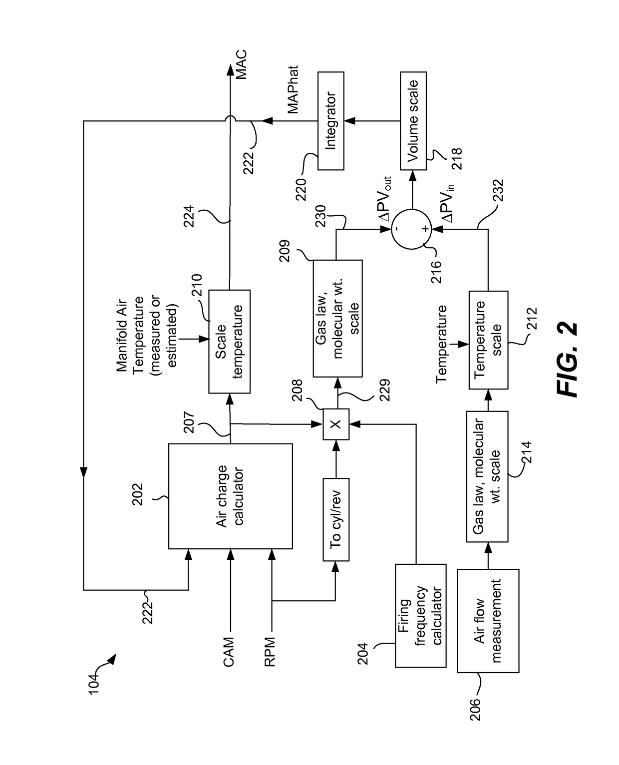
[0016]The present invention relates generally to models for estimating mass air charge and / or manifold absolute pressure for a wide variety of powertrain, engine and diagnostic applications. Such models can be particularly useful in skip fire and variable displacement engine control.

[0017]Various conventional approaches for estimating mass air charge rely on the direct measurement of the pressure in the intake manifold. This approach works well in situations in which the manifold absolute pressure does not frequently change. However, in some applications such as dynamic skip fire engine operation, air is not steadily and predictably withdrawn from the intake manifold into the working chambers of the engine for combustion. Working chambers may be individually controlled and decisions to “skip” (i.e., deactivate) or fire individual working chambers may be made in real time. Under such circumstances, the manifold absolute pressure may fluctuate in an unpredictable manner due to variabl...


PUM


Abstract

In one aspect, an engine controller for an engine including multiple working chambers is described. The engine controller includes a mass air charge determining unit that estimates a mass air charge or amount of air to be delivered to a working chamber. Firing decisions made for a firing window of one or more firing opportunities are used to help determine the mass air charge. The engine controller also includes a firing controller, which is arranged to direct firings to deliver a desired output. Fuel is delivered to a working chamber based on the estimated mass air charge.

Description

FIELD OF THE INVENTION[0001]The present invention relates generally to methods and mechanisms for estimating manifold air pressure and / or mass air charge. Various embodiments involve using such estimates to help improve engine performance, particularly in variable displacement or skip fire applications.BACKGROUND[0002]Most vehicles in operation today are powered by internal combustion (IC) engines. Internal combustion engines typically have multiple cylinders or other working chambers where combustion occurs. The power generated by the engine depends on the amount of fuel and air that is delivered to each working chamber. The mass of air delivered into each working chamber per intake event is referred to as the mass air charge.[0003]Air is typically delivered into the working chamber from an intake manifold. A throttle valve helps regulate the delivery of air from the outside environment into the intake manifold. Opening the throttle causes more air to enter the intake manifold, whi...

Claims


Application Information

Patent Timeline
Patent Type & Authority Patents(United States)
IPC IPC(8): F02D7/00F02D41/18F02D35/02
CPCF02D41/18F02D2200/0408F02D2200/0402F02D35/028
Inventor KOTWICKI, ALLAN J.VAN ESS, JOEL D.
Owner TULA TECH INC
Why Eureka
Try Eureka