
Disinfecting methods and apparatus

a technology applied in the field of disinfection methods and utensils, can solve the problems of unwanted and dangerous bacteria growth on or in the equipment or components of the commonly used treatment device for patients, and the equipment or components of water processing plants, livestock habitation facilities, etc., and achieves severe side effects

Active Publication Date: 2018-03-27
ZABORSKY BRETT
View PDF39 Cites 0 Cited by
  • Summary
  • Abstract
  • Description
  • Claims
  • Application Information

AI Technical Summary

Benefits of technology

The patent text discusses the benefits of using light to kill bacteria instead of pharmacological or chemical agents. The main advantage is that light is less likely to cause resistance in bacteria, which can make antimicrobial agents less effective over time. Light treatment also avoids the side effects that can occur with many chemical agents.

Problems solved by technology

Unwanted and dangerous bacteria growth can occur on or in devices that are commonly used to treat patients.
Hospital acquired infections account for a substantial yearly expense to hospitals and insurance companies, and are a major cause of extending hospital stays for patients.
Equipment or components of water processing plants, food processing plants, dairies, livestock habitation facilities, etc. are also susceptible bacteria growth.

Method used


Image

  • Disinfecting methods and apparatus
  • Disinfecting methods and apparatus
  • Disinfecting methods and apparatus

Examples


Embodiment Construction

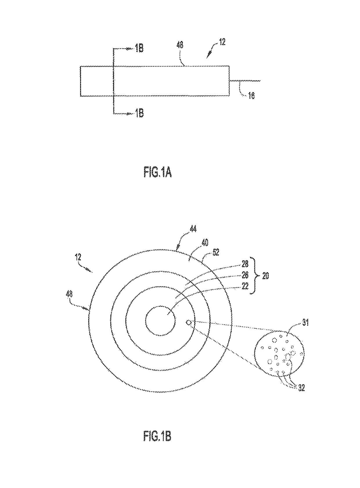
[0072]FIG. 1A is a schematic side view of a radially emitting fiber with a plurality of voids in the core of the radially emitting optical fiber 12 having a central axis 16. FIG. 1B is a schematic cross-section of a radially emitting optical fiber 12 as viewed along the direction 1B-1B in FIG. 1A. Radially emitting fiber 12 can be, for example, an optical fiber with a nano-structured fiber region having periodic or non-periodic nano-sized structures 32 (for example voids). In an example implementation, fiber 12 includes a core 20 divided into three sections or regions. These core regions are: a solid central portion 22, a nano-structured ring portion (inner annular core region) 26, and outer, solid portion 28 surrounding the inner annular core region 26. A cladding region 40 surrounds the annular core 20 and has an outer surface. The cladding 40 may have low refractive index to provide a high numerical aperture. The cladding 40 can be, for example, a low index polymer such as UV or ...


PUM


Abstract

According to one implementation an assembly is provided that includes a first and second optical fibers and a body that has respective first and second lumens in which at least a portion of the length of the first and second optical fiber reside. The first optical fiber is an end emitting fiber that is configured to end emit bacterial disinfecting light to disinfect at least a first portion of the body, and the second optical fiber is a radial emitting fiber that is configured to radially emit bacterial disinfecting light to disinfect at least a second portion of the body.

Description

TECHNICAL FIELD[0001]The present disclosure relates to devices having disinfecting capabilities and to methods for disinfecting any of a host of devices including, for example, devices used in the medical treatment of patients.BACKGROUND[0002]Unwanted and dangerous bacteria growth can occur on or in devices that are commonly used to treat patients. These devices may include central venous catheters, urinary catheters, ventilators, wound protection devices, etc. Hospital acquired infections account for a substantial yearly expense to hospitals and insurance companies, and are a major cause of extending hospital stays for patients. Equipment or components of water processing plants, food processing plants, dairies, livestock habitation facilities, etc. are also susceptible bacteria growth.SUMMARY OF THE DISCLOSURE[0003]According to some implementations disclosed herein light is used to disinfect the internal and / or external surfaces of devices used in the medical treatment of patients...

Claims


Application Information

Patent Timeline
Patent Type & Authority Patents(United States)
IPC IPC(8): A61L2/00A61M39/16A61N5/06A61M25/00
CPCA61L2/0023A61L2/0047A61M39/16A61N5/0624A61M2025/0019A61B1/07A61L2/10G02B6/102A61M25/0026A61M2025/004A61M25/0097A61L2/26A61L2202/14A61L2202/24A61L2202/11A61B1/012A61B1/018A61B1/015G02B6/036G02B6/0229G02B6/001A61M2209/10A61M39/284G02B1/045A61L2/084A61L2202/16A61L2/08A61M39/28G02B6/02G01M11/31
Inventor ZABORSKY, BRETT M.LOPEZ, MICHAEL R.LAROYA, GIL
Owner ZABORSKY BRETT
Learn More