
Combination low-pass filter

a low-pass filter and filter technology, applied in the field of low-pass filtering, can solve the problems of brickwall-type filters that are known to generate excessive ringing on either side, no filter is ideal, and present artifacts or defects, and achieve the effect of reducing the bandwidth of input signals

Active Publication Date: 2018-03-20
FAROUDJA YVES
View PDF5 Cites 0 Cited by
  • Summary
  • Abstract
  • Description
  • Claims
  • Application Information

AI Technical Summary

Benefits of technology

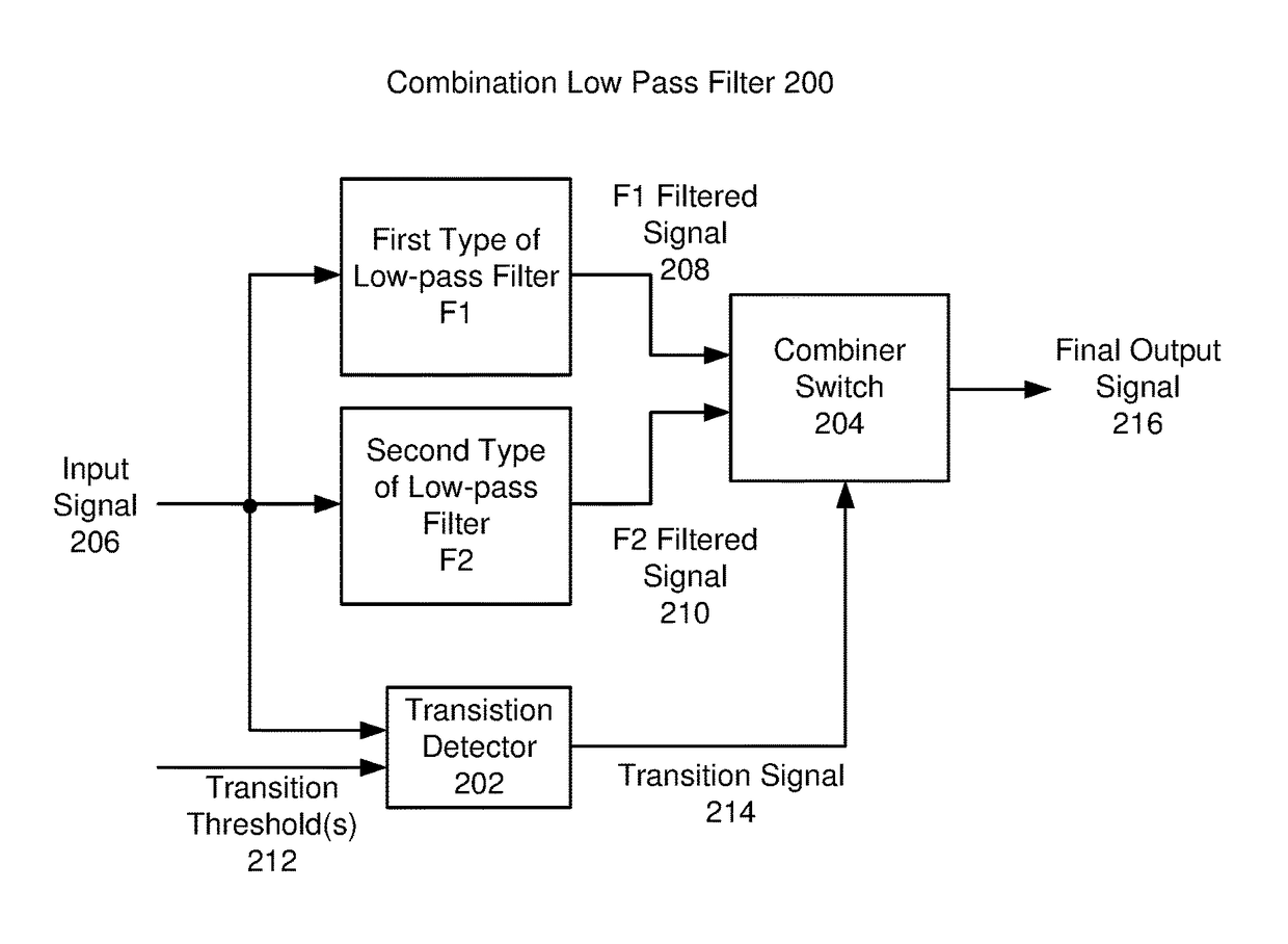
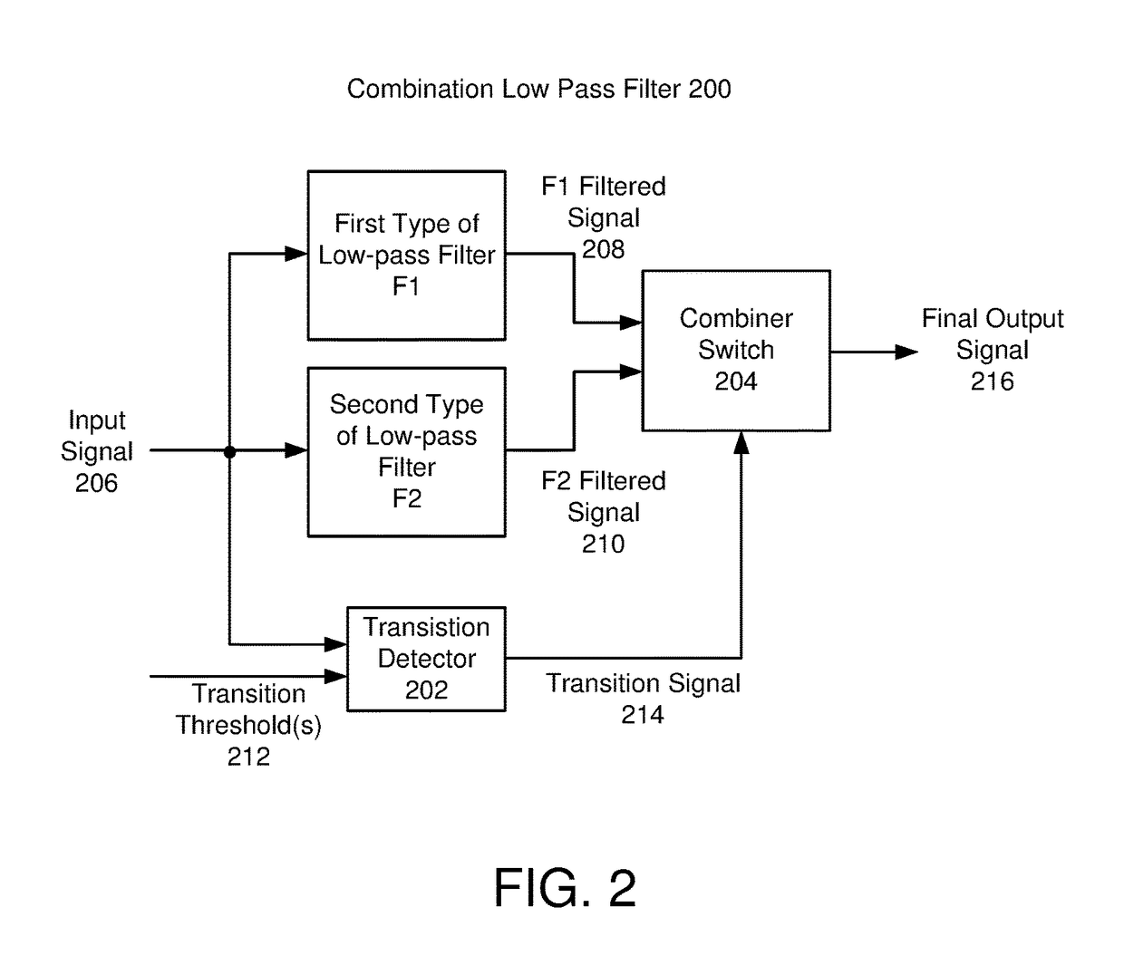
The patent text describes a method and system for reducing the bandwidth of an input signal using a combination of two types of low-pass filters. The first filter produces a signal with a unique set of artifacts, while the second filter is designed to not have these artifacts. When there is no significant transition in the input signal, the first filtered signal is output. However, when a significant transition is detected, the first filtered signal is selectively replaced with parts of the second filtered signal to minimize the impact of the unique artifacts. This method combines the characteristics of two different types of low-pass filters to better control the bandwidth of the input signal.

Problems solved by technology

In practice, no filter is ideal.
Unfortunately, both types of low pass filters (including other filters having the same family of responses as Brick-wall filters and Gaussian filters) present artifacts or defects, particularly in the time domain in video and audio signal examples.
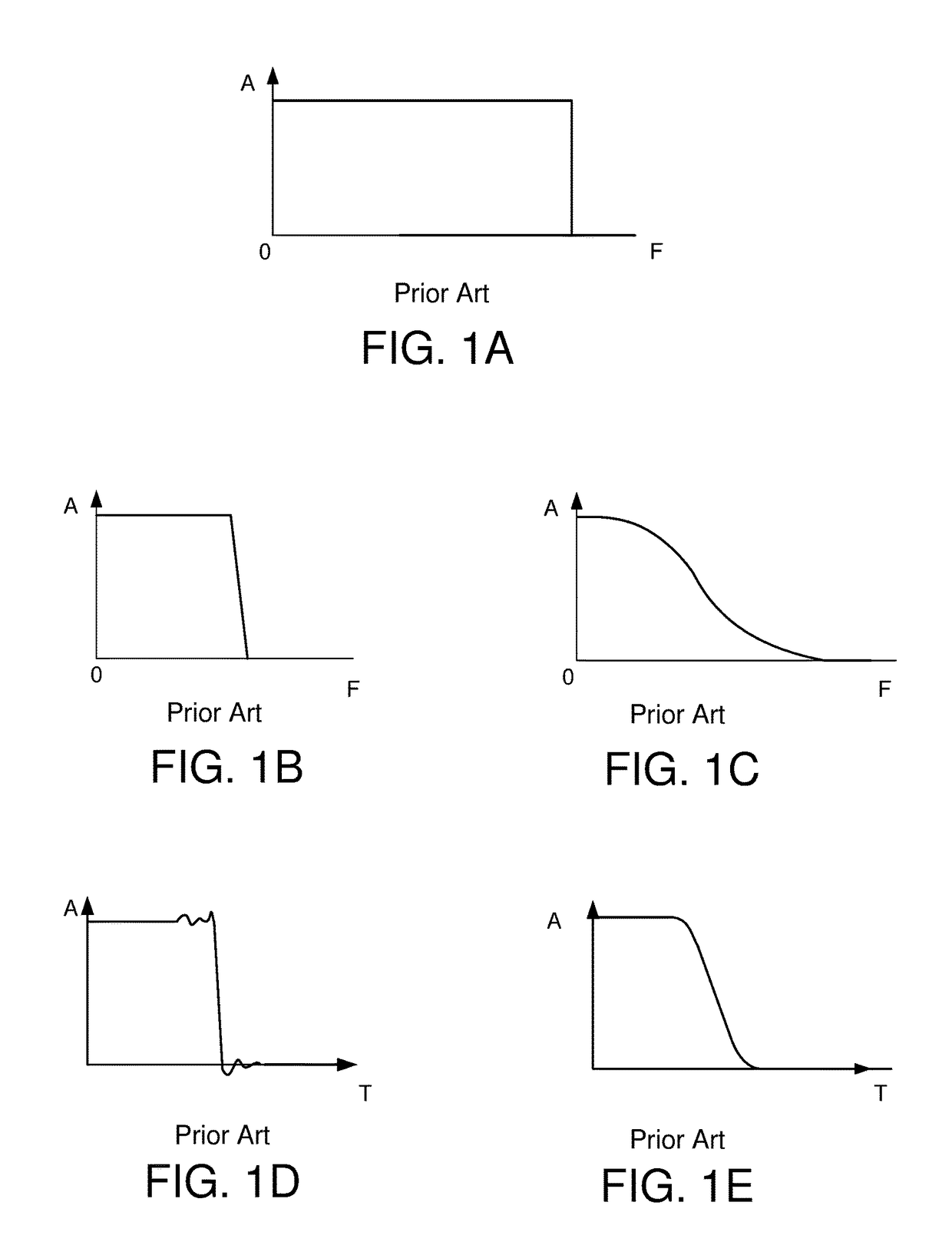
For example, Brickwall-type filters are known to generate excessive ringing on either side of large amplitude transitions, which is detrimental to image appearance. FIG. 1D is a time domain representation of the output of the ideal Brickwall-type low-pass filter after processing the signal of FIG. 1A, where the x-axis represent frequency and the y-axis represents time.
The inconvenience is that due to the impulse response function of the Brickwall filter, the Brickwall filter produces time domain artifacts called “ringing” in the vicinity of the cutoff area, i.e., on either side of the transition in the input signal.
The high frequencies are not sufficiently attenuated (which leads to undesirable artifacts with further processing) and, in video for example, a sudden transition in the input signal is expanded in time in the output signal (FIG. 1E), which makes the image appear to be out of focus in the vicinity of the transition.

Method used


Image

  • Combination low-pass filter
  • Combination low-pass filter
  • Combination low-pass filter

Examples


Embodiment Construction

[0023]The following description is presented to enable one of ordinary skill in the art to make and use the invention and is provided in the context of a patent application and its requirements. Various modifications to the exemplary embodiments and the generic principles and features described herein will be readily apparent. The exemplary embodiments are mainly described in terms of particular methods and systems provided in particular implementations. However, the methods and systems will operate effectively in other implementations. Phrases such as “exemplary embodiment”, “one embodiment” and “another embodiment” may refer to the same or different embodiments. The embodiments will be described with respect to systems and / or devices having certain components. However, the systems and / or devices may include more or less components than those shown, and variations in the arrangement and type of the components may be made without departing from the scope of the invention. The exempl...


PUM


Abstract

A combination low-pass filter and a method for reducing bandwidth of an input signal comprises filtering an input signal in parallel with a first type of low-pass filter to produce a first filtered signal having the first type of artifacts, and a second low-pass filter to produce a second filtered signal that does not include the first type of artifacts. Responsive to detecting no significant transition in the input signal, the first filtered signal is output. And responsive to detecting a significant transition in the input signal, portions of the first filtered signal are selectively replaced with portions of the second filtered signal by switching outputs from the first filtered signal to the second filtered signal in transition zones occurring immediately before and immediately after the detected transition in the input signal, wherein the transition zones overlap duration of the first type of artifacts caused by the first filter.

Description

BACKGROUND[0001]Low pass filters are used in all branches of signal processing (video, audio, data, etc.). Their function is to pass a package of wave energy from zero frequency up to a determined cut-off frequency and reject all energy beyond this limit. An ideal low-pass filter is one that passes, without attenuation, all frequencies below the cut-off frequencies while providing infinite attenuation above the cut-off frequencies.[0002]FIG. 1A is a frequency domain representation of a portion of a conventional input signal where a sharp transition occurs, where the x-axis represent frequency and the y-axis represents amplitude. For many applications, the input signal may be bandwidth reduced using some type of low-pass filter. However, depending on their structure, low-pass filters may react differently during the processing of a very sharp transition in the input signal, e.g., an abrupt change between black and white. For the sake of simplicity, the example signal shown is limited...

Claims


Application Information

Patent Timeline
Patent Type & Authority Patents(United States)
IPC IPC(8): H04B1/66H04B14/04H03H17/04H04N19/90H03M7/30
CPCH04B14/046H04B1/66H03H17/0416H04N19/90H03M7/3053H04N19/172H04N19/117H04N19/142H04N19/85
Inventor FAROUDJA, YVES
Owner FAROUDJA YVES
Learn More