
Adjustable sliding screen apparatus

a sliding screen and adjustment technology, applied in the direction of aircraft crew accommodation, wing accessories, seating arrangements, etc., can solve the problems of affecting the safety of passengers, so as to achieve easy and quick adjustment, reduce the effect of weight and space requirements, and reduce the number of machine parts

Active Publication Date: 2018-03-20
BE AEROSPACE INCORPORATED
View PDF36 Cites 6 Cited by
  • Summary
  • Abstract
  • Description
  • Claims
  • Application Information

AI Technical Summary

Benefits of technology

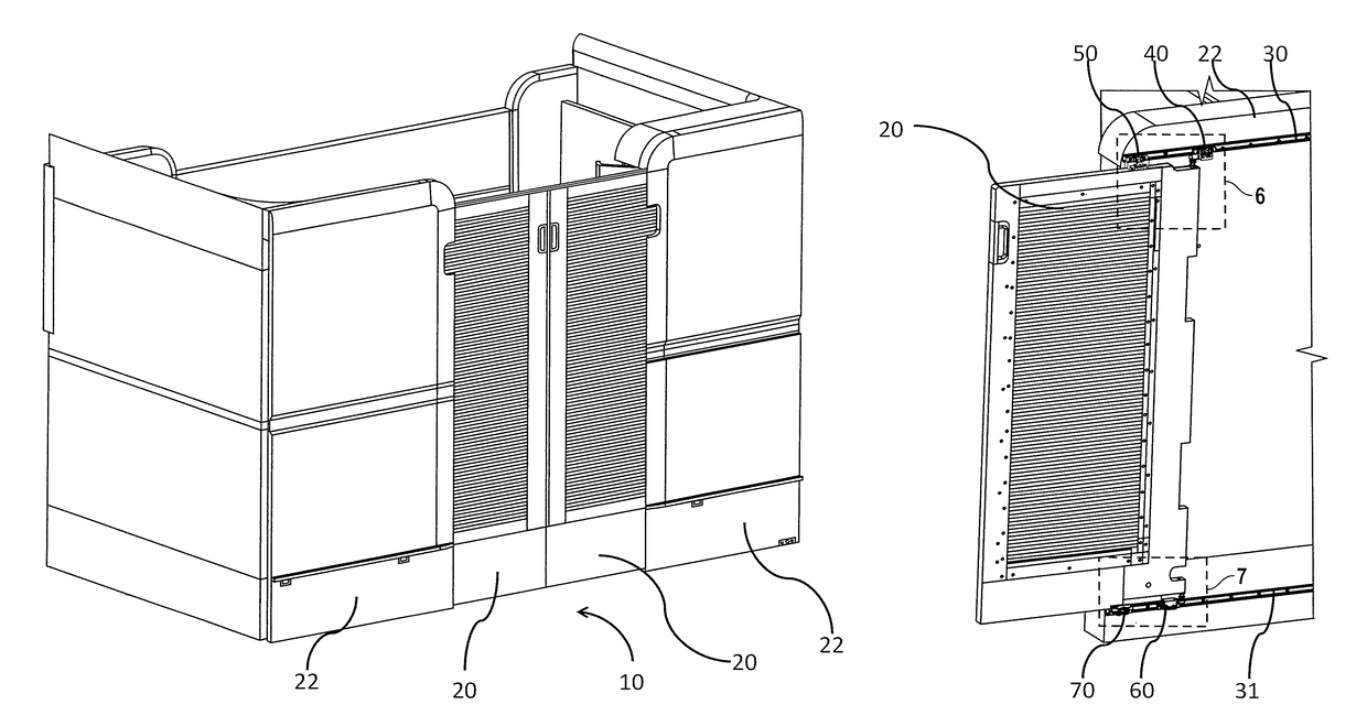
[0007]It is therefore an object of the present invention to provide an adjustable sliding privacy screen apparatus for a vehicle which may easily and quickly be adjusted. It is another object of the present invention that the adjustable sliding privacy screen apparatus may be lightweight and have a low profile. It is a further object of the invention to provide an apparatus that has few machined parts. It is a further object of the present invention that the apparatus be configured to adjust the pitch, roll, and yaw of the privacy screen.
[0012]According to another aspect of the invention, the apparatus is very compact having a small envelope. The invention is versatile and may be used on many different types of screens / doors with only minor screen design changes. The invention is optimized for strength and may include a small number of parts including as few as 6 machined parts per screen.
[0014]According to one embodiment of the invention, one of the adjustable brackets is a yaw / roll bracket which facilitates adjustment of the yaw and roll of the screen. The other adjustment bracket is a ball joint bracket which facilitates adjustment of the pitch of the door and also accommodates adjustment of the yaw / roll bracket.
[0019]According to another embodiment of the invention, the ball joint bracket includes a carriage connected to the truck and a ball joint connected to the carriage and also to the screen / door. The ball joint bracket also includes an adjustable nut for adjusting the length of the ball joint which imparts an adjustment to the pitch of the screen / door. The ball joint further includes a locking nut which secures the position of the ball joint relative the screen / door and the carriage.
[0024]According to another embodiment of the invention, the screen is made from lightweight materials and has a low profile relative the fixed partition.
[0033]According to another embodiment of the invention, the screen may be made of lightweight materials and may have a low profile relative the fixed partition.

Problems solved by technology

While passengers have come to expect certain amenities, the inclusion of amenities comes with additional cost, weight, complexity, and space requirements.
However, adding doors and walls to aircraft interiors can be bulky and heavy—both features which it is desirable to minimize.
Further, as aircraft and other vehicles are frequently in motion including acceleration, deceleration, and maneuvers, aircraft interiors experience forces which cause contents of the aircraft to jostle and move.
In some cases, even interior fixtures such as doors and privacy screens may move out of alignment and require adjustment.
The door's pitch, yaw, and roll are subject to change and may need realignment.
Current mechanisms for adjusting the position and angles of sliding screens (for alignment) are difficult to adjust, take up large amounts of space and usually need to be tailored to specific screen configurations.
Further, because aircraft have little downtime between flights—such as flights were a suite's privacy doors may have become out of alignment—there is a need in the art for a door adjustment mechanism that may quickly be adjusted.

Method used


Image

  • Adjustable sliding screen apparatus
  • Adjustable sliding screen apparatus
  • Adjustable sliding screen apparatus

Examples


Embodiment Construction

[0052]The present invention will now be described more fully hereinafter with reference to the accompanying drawings in which exemplary embodiments of the invention are shown. However, the invention may be embodied in many different forms and should not be construed as limited to the representative embodiments set forth herein. The exemplary embodiments are provided so that this disclosure will be both thorough and complete, and will fully convey the scope of the invention and enable one of ordinary skill in the art to make, use and practice the invention. Like reference numbers refer to like elements throughout the various drawings.

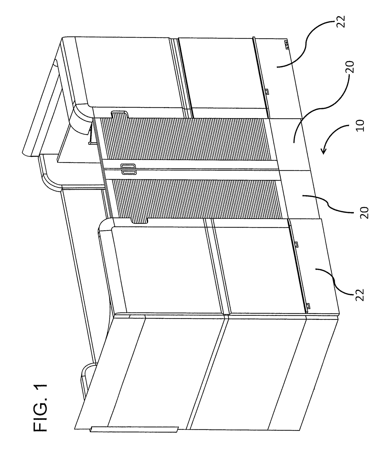
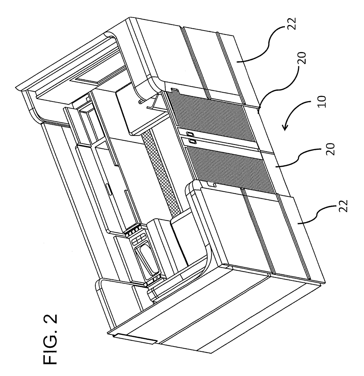
[0053]Referring to the figures, provided herein are various embodiments of passenger suite seating arrangements, for example, for installation within an aircraft or other conveyance. The term “suite” as used herein includes individual passenger living compartments or living spaces generally including adjustable seats, working surfaces, tray tables, video...


PUM


Abstract

An adjustable sliding privacy screen for a premium class passenger suite may include a guide rail mounted to a wall partition. The adjustable sliding privacy screen may also include a yaw and roll adjustment bracket slidingly attached to the guide rail and to the screen. The yaw and roll adjustment bracket may include a flanged adjustment screw for adjusting the yaw and roll of the screen and a locking screw for securing the yaw and roll adjustment of the screen. The screen may also include a ball joint adjustment bracket slidingly attached to the guide rail and to the screen. The ball joint adjustment bracket may include a ball joint and adjustment screw for adjusting the pitch of the screen and a locking nut for securing the pitch adjustment of the screen. The device of the present invention thus allows for the adjustment of the yaw, roll, and pitch of the screen.

Description

CROSS-REFERENCE TO RELATED APPLICATIONS[0001]This application is a non-provisional patent application which traces priority to and incorporates by reference the entirety of U.S. provisional application having application No. 62 / 145,157 filed on Apr. 9, 2015.TECHNICAL FIELD AND BACKGROUND OF THE INVENTION[0002]The present invention relates generally to compartment closure mechanisms and more particularly to closure mechanisms for use in vehicle compartments. The invention is an adjustable sliding apparatus for doors, screens, privacy partitions, and the like for use in vehicles. As used herein, the term door or the term screen will be synonymous with one another and also inclusive of any and all other such moveable privacy partitions.[0003]Premium passenger seating arrangements in aircraft can take the form of individual suites separated and defined by walls and partitions. Such suites typically include a passenger living area outfitted with comfort, luxury, and convenience features ...

Claims


Application Information

Patent Timeline
Patent Type & Authority Patents(United States)
IPC IPC(8): B64C1/14E05D15/06B64D11/06E06B3/46
CPCE05D15/0643B64C1/1438B64D11/0606E05D15/0678E06B3/4636E05D15/0656E05Y2900/502
Inventor DRUCKMAN, DAVID J.FROST, IAN L.
Owner BE AEROSPACE INCORPORATED
Learn More