
Collaboration method and system in distributed resilient network interconnect system

Inactive Publication Date: 2018-02-27
ZTE CORP
View PDF4 Cites 1 Cited by
  • Summary
  • Abstract
  • Description
  • Claims
  • Application Information

AI Technical Summary

Benefits of technology

The present patent explains a way to collaborate between different computer systems in a way that protects the interface between them. This is done by combining the systems into a logical system that can be easily managed and protected. This allows for better security and efficiency in the use of multiple computer systems.

Problems solved by technology

The current IEEE standard 802.1AX link aggregation can achieve protection for multiple links, but is limited to supporting only the port aggregation on one node, therefore it can only be used for link protection, while using the current link aggregation technology cannot protect the node on the network edge interface.

Method used


Image

  • Collaboration method and system in distributed resilient network interconnect system
  • Collaboration method and system in distributed resilient network interconnect system
  • Collaboration method and system in distributed resilient network interconnect system

Examples


first embodiment

The First Embodiment

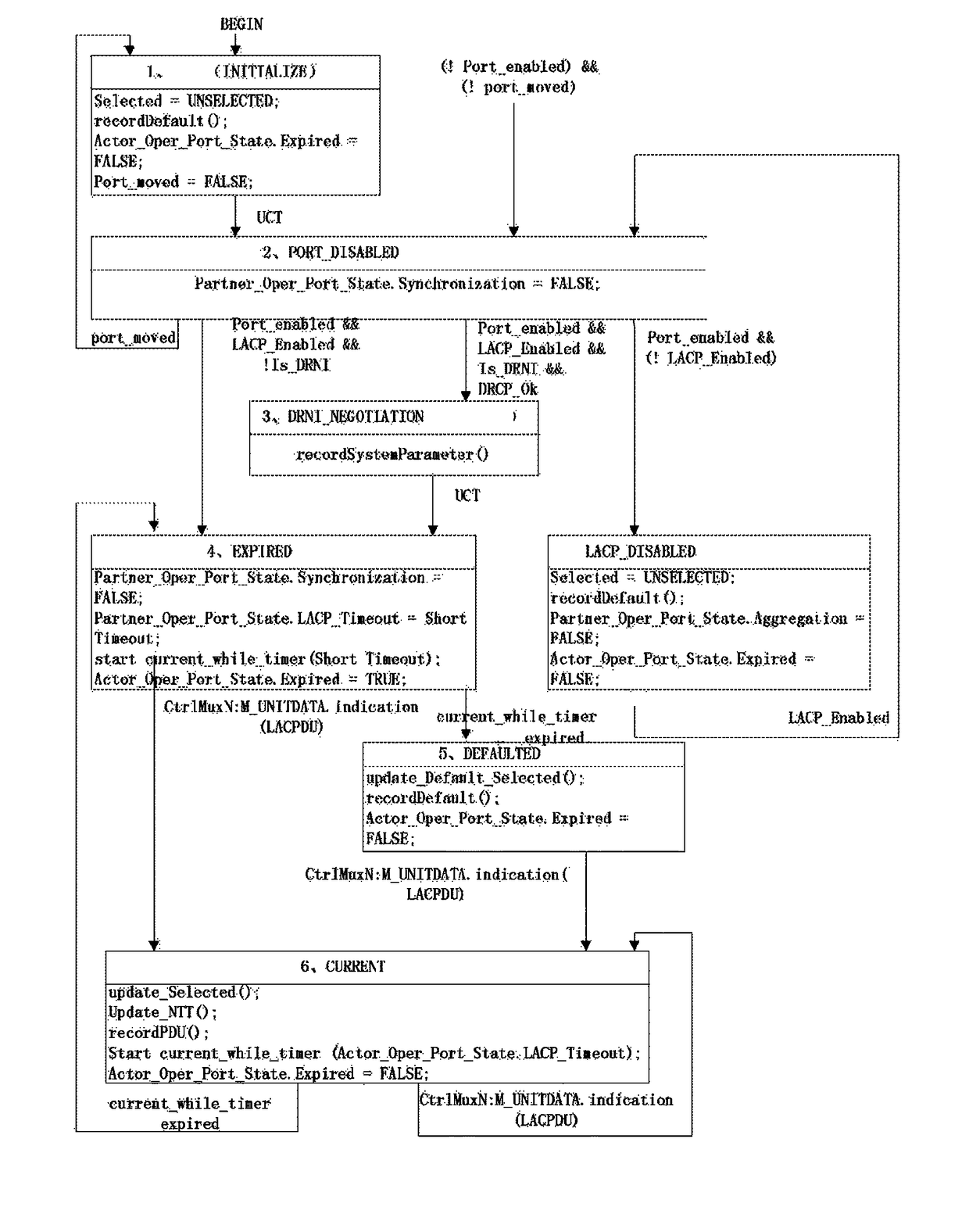
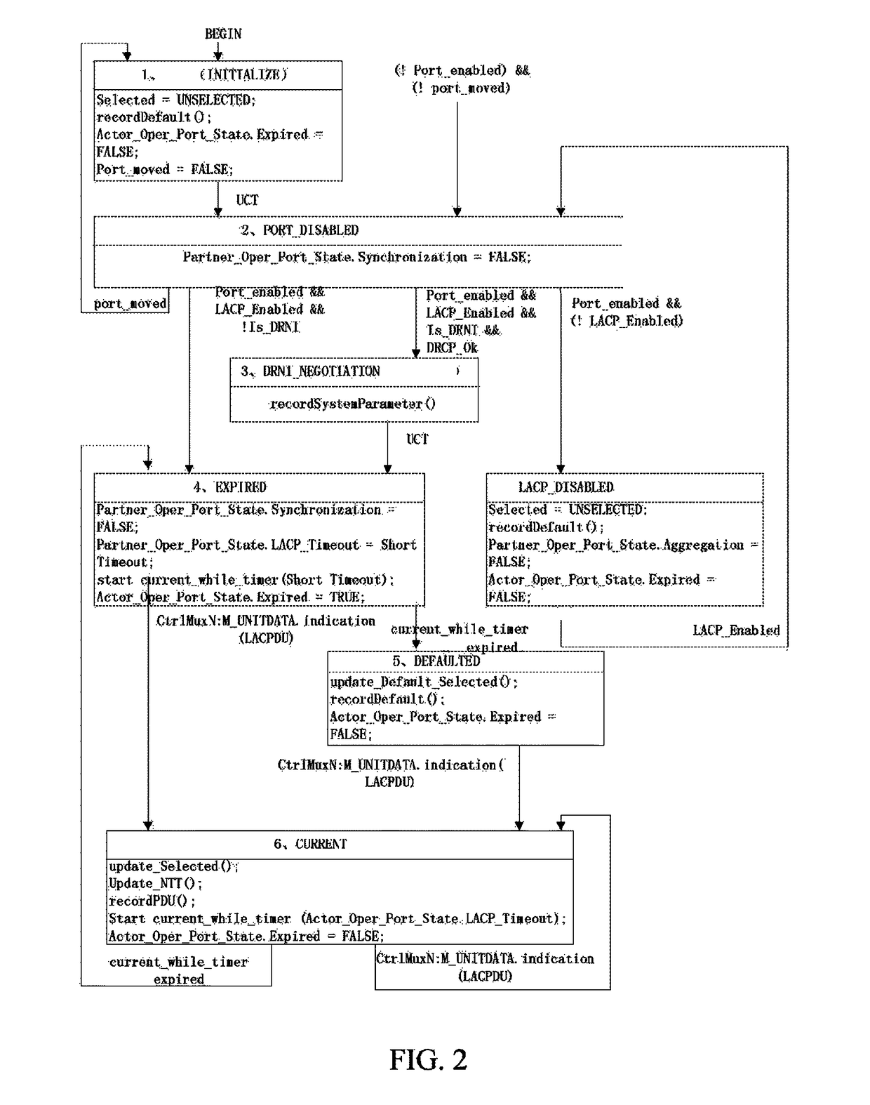
[0084]FIG. 2 is a schematic diagram of a machine state transition of a receiving state machine. The functions of the receiving state machine comprise processing the received LACP packets, parsing the packets, recording aggregation-related information of the partner, and calling the selection logic module to set the selected state of the port, setting the link aggregation related data according to the information of the partner, and making an appropriate treatment by judging whether the aggregation related data of the partner stored in the actor is aging, and motivating other state machines of the LACP protocol to operate. It is the core of the group of state machines of the LACP protocol.

[0085]1. INITIALIZE State

[0086]parameters under this state comprise: Selected parameter

[0087]the INITIALIZE state initializes some parameter variables, it takes the partner parameter administrative value as the current operating value, and sets the Selected parameter to UNSELECTE...

second embodiment

The Second Embodiment

[0104]FIG. 3 is a schematic diagram of state transition of a periodic transmitting state machine.

[0105]The periodic transmitting state machine is configured to determine that the actor and the partner need to exchange the LACPDUs on the link in order to maintain the aggregation, and determine how long the periodic transmitting should occur. If either port needs, the periodic transmitting will occur. The transmission period is determined by the partner; this period is related to the rate of the receiving information timeout of the partner.

[0106]The periodic transmitting state machine is further configured to decide whether the periodic transmitting occurs in accordance with the DRCP relevant system parameters.

[0107]If the DRNI is not supported (Is_DRNI=FALSE), the periodic transmitting occurs when the values of both the LACP_Enabled and the portal_enabled are TRUE, and one of the Partner_Oper_Portal_State.LACP_Activity and the Actor_Oper_Portal_State.LACP_Activit...

third embodiment

The Third Embodiment

[0115]FIG. 4 is a schematic diagram of a state transition of a multiplexing state machine. The multiplexing state machine is set to decide whether to block the port to control the enabling and disabling of the functions of receiving and transmitting data of the port based on the selected states of the actor and the partner. In this state, the port state change is notified to the DRCP module in real-time.

[0116]1. DETACHED State

[0117]The Selected variable changes to the UNSELECTED or STANDBY state, which causes the state machine to enter into the DETACHED state. The process of detaching the port from the aggregator begins. Once the detaching process is completed, the value of the Actor_Oper_Portal_State.Synchronization is set to FALSE, indicating that the actor considers that the port is OUT_OF_SYNC, and the frame distribution function of the port is disabled, values of the Actor_Oper_Portal_State.Distributing and the Actor_Oper_Portal_State.Collecting are set to F...


PUM


Abstract

The embodiment of the present document provides a collaboration method in a distributed resilient network interconnected system, including: a link aggregation control protocol (LACP) system receiving system parameters notified by a distributed relay control protocol (DRCP) system, and using the system parameters of the DRCP system as system negotiation parameters of the LACP system. The embodiments of the present document further provide a link aggregation control protocol (LACP) system, wherein the LACP system includes a receiving module and a controlling module, the receiving module is configured to receive system parameters notified by a distributed relay control protocol (DRCP) system; the controlling module is configured to take the system parameters of the DRCP system as system negotiation parameters of the LACP system. The embodiment of the present document achieves a collaboration between the LACP system and the DRCP system.

Description

CROSS-REFERENCE TO RELATED APPLICATION(S)[0001]This application is the U.S. National Phase application of PCT application number PCT / CN2014 / 076008 having a PCT filing date of Apr. 23, 2014, which claims priority of Chinese patent application 201310247572.5 filed on Jun. 20, 2013, the disclosures of which are hereby incorporated by reference.TECHNICAL FIELD[0002]The present document relates to data communication technology, and more particularly, to a collaboration method and system in a distributed resilient network interconnected system.BACKGROUND OF RELATED ART[0003]The Ethernet link aggregation is called Link Aggregation, which bundles multiple Ethernet physical links together into one logical link, so as to achieve the purpose of increasing the link bandwidth. At the same time, these bundled links are dynamically backed up each other, which can effectively improve the link reliability. The LACP (Link Aggregation Control Protocol) is a protocol that is based on the IEEE (Institut...

Claims


Application Information

Patent Timeline
Patent Type & Authority Patents(United States)
IPC IPC(8): H04L12/24H04L29/06H04L12/709H04L45/243
CPCH04L41/0836H04L69/14H04L45/245H04L41/0893Y02D50/30Y02D30/50
Inventor GUO, ZHUIWEI, YUEHUAAO, TING
Owner ZTE CORP
Learn More