
Vehicle mounted electronic device enclosure

Inactive Publication Date: 2018-02-20
RUIZ STEVE
View PDF6 Cites 16 Cited by
  • Summary
  • Abstract
  • Description
  • Claims
  • Application Information

AI Technical Summary

Benefits of technology

The patent describes a system that stops people from using electronic devices while driving a car. This is done by using a special enclosure that makes it difficult for the driver to access the device while the car is in use. The technical effect of this system is to improve safety and reduce the risk of accidents caused by drivers using electronic devices while driving.

Problems solved by technology

Distracted driving is a major problem, leading to countless injuries and deaths, as well as significant property damage.
The problem is significant enough that legislation has been enacted nationwide to make it unlawful to engage in cell phone use while driving.
Such businesses are legally responsible for the conduct of their employees carried out in the course of business, and will incur significant financial responsibility when an accident occurs and someone is injured by their employee.
Aside from the resulting increase in insurance rates and responsibility for losses beyond insurance coverage, an accident caused by one of their employees can result in devastatingly bad publicity for the company.
As a result, companies have struggled to find an effective solution to prevent electronic device usage by their employees while driving.
But none of these measures seem effective at stopping their employees from making a momentary exception to ‘just check their phone’.
While these units may be suitable for the particular purpose employed, or for general use, they would not be as suitable for the purposes of the present disclosure as disclosed hereafter.

Method used


Image

  • Vehicle mounted electronic device enclosure
  • Vehicle mounted electronic device enclosure
  • Vehicle mounted electronic device enclosure

Examples


Embodiment Construction

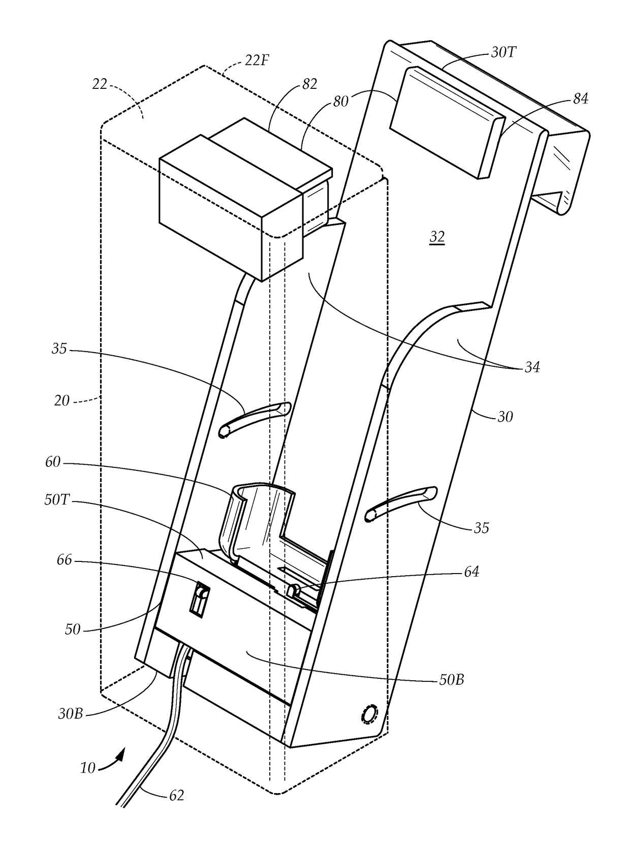
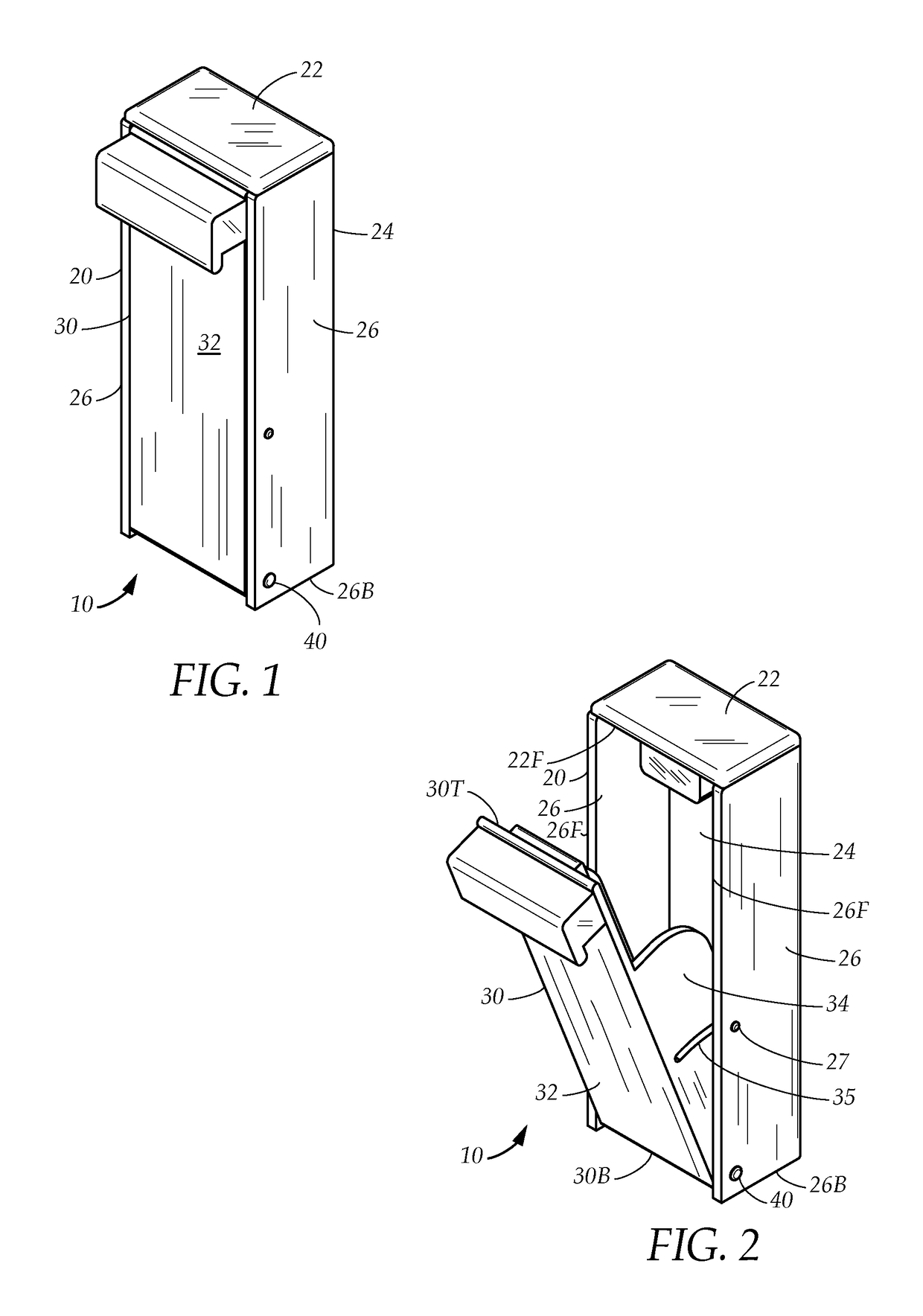
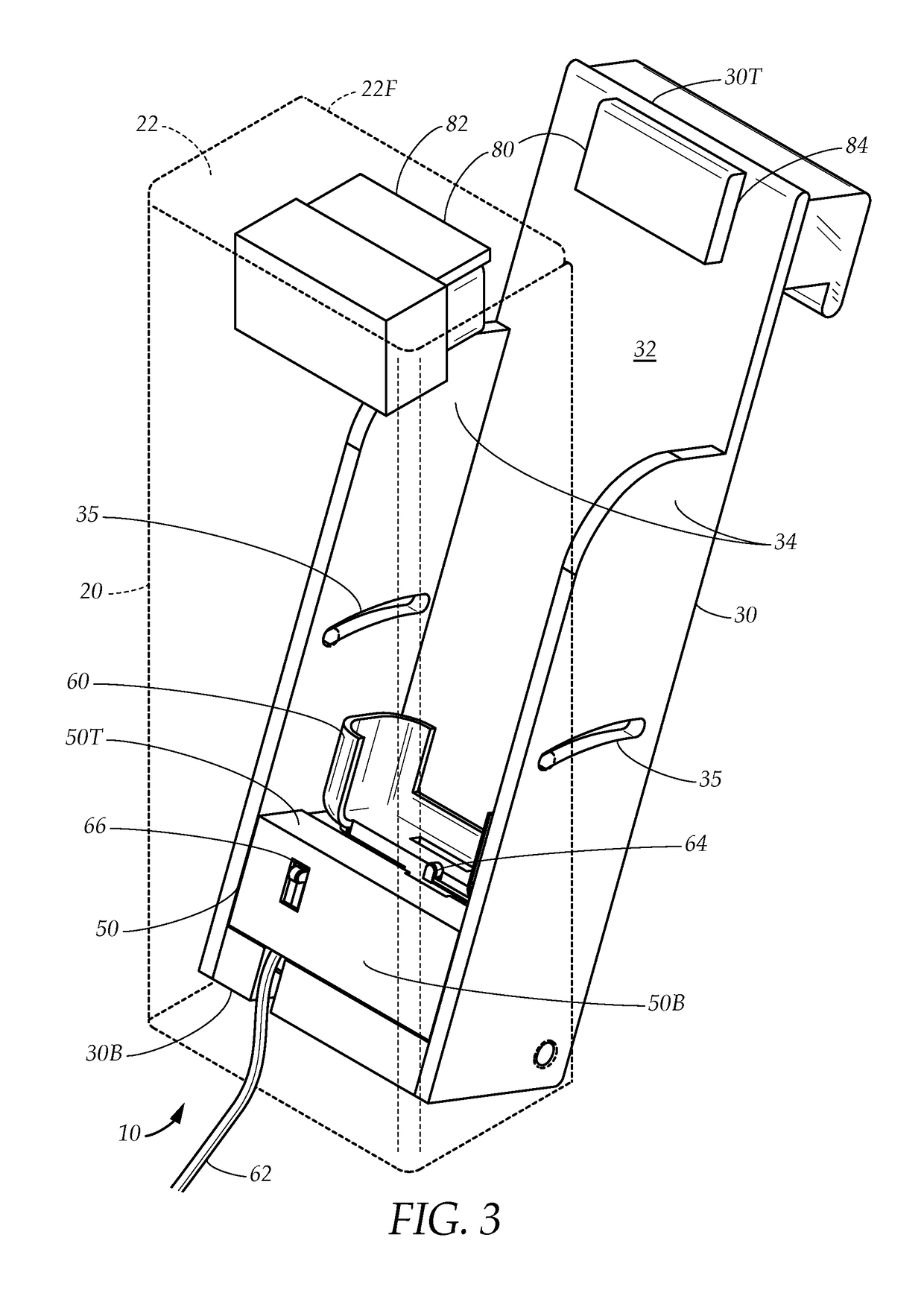
[0024]FIG. 1 and FIG. 2 illustrate an electronic device enclosure 10 having a main part 20, and a door 30. The main part 20 includes a top panel 22, a rear panel 24, and a pair of main side panels 26 that meet orthogonally and are secured together. The top panel 22 and main side panels 26 have front edges 22F, 26F, such that the main part is open at the front edges 22F, 26F and substantially closed at the rear panel 24. The door 30 includes a front panel 32, and at least one door side panel 34. The door 30 has a top edge 30T and a bottom edge 30B. The door 30 is hingedly attached to the main part 20 along the bottom edge 30B, such that the door 30 has an open position wherein it extends angularly away from the main part 20 from near the bottom edge 30B, and a closed position wherein the front panel 32 extends substantially coincident with the front edges 22F, 26F of the top 22 and sides 26 of the main part 20.

[0025]The door 30 is hingedly attached to the main part 20, and the door 3...


PUM


Abstract

An enclosure for use in a vehicle having an ignition system, for securely holding an electronic device and rendering it inaccessible during operation of the vehicle. The enclosure has a main part and a door. The door has an open position and a closed position and includes a device cradle for holding the electronic device. A device responsive switch is closed when the electronic device is located within the device cradle, and a door responsive switch is closed when the door is in the closed position. When the ignition is on, the door responsive switch and device responsive switch must both be closed for the vehicle to operate. A locking assembly holds the door in the closed position and is activated while the vehicle is in operation to physically prevent access to the electronic device while the vehicle is in operation.

Description

TECHNICAL FIELD[0001]The present disclosure relates generally to an electronic device enclosure. More particularly, the present disclosure relates to a system for preventing electronic device usage while operating a motor vehicle, by requiring the electronic device to be locked within the enclosure while the vehicle is in operation.BACKGROUND[0002]Distracted driving is a major problem, leading to countless injuries and deaths, as well as significant property damage. Today, the most common form of distracted driving results from talking or texting with a cellphone. The problem is significant enough that legislation has been enacted nationwide to make it unlawful to engage in cell phone use while driving.[0003]For businesses that operate fleets of vehicles, having their employees operate vehicles while distracted by electronic devices is a major concern. Such businesses are legally responsible for the conduct of their employees carried out in the course of business, and will incur sig...

Claims


Application Information

Patent Timeline
IPC IPC(8): H04M1/667B60R11/02B60R11/00
CPCH04M1/667B60R11/0241B60R11/0264B60R2011/0005H04M1/04B60R2011/0075B60R2011/0094
Inventor RUIZ, STEVE
Owner RUIZ STEVE
Learn More