
Piping assembly control system with addressed datagrams

a control system and datagram technology, applied in the field of methods and apparatus for controlling the operation of piping assemblies, can solve the problems of insufficient datagram use, insufficient depth, and insufficient depth of cased wells, and achieves the effects of short length, reduced inconvenient operation, and reduced inconvenient us

Active Publication Date: 2018-02-20
AOI ADVANCED OILFIELD INNOVATIONS
View PDF82 Cites 0 Cited by
  • Summary
  • Abstract
  • Description
  • Claims
  • Application Information

AI Technical Summary

Benefits of technology

The present invention is a new and improved downhole control system that allows for the use of numerous tools with specific addresses in a single trip into the well. This system uses low level pressure pulses to control valves and can be used in both deep cased wells and open holes. The system is compact and reliable, and reduces operating time and complicated sequencing of high level annulus pressure applications. Overall, the invention simplifies downhole tool components, increases reliability, and allows for greater efficiency in well services.

Problems solved by technology

However, in the past, some very deep, cased wells were not tested with pressure controlled tools because the operating pressure would have exceeded the burst rating of the casing.
Until this was possible, certain types of valve devices, such as circulating valves and some sliding valves required lengthy operating times due to the complicated series of annulus or tubing pressure changes required to cycle the tool from the closed to opened positions and back again.
The older designs required dimensional lengths that often became excessive, to the point where a typical combination of tester, sampler and circulating valves could and in some cases still do require lengths in excess of 200-300 feet.
Increased complexity of valve systems reduces their reliability, and increases the chances of mishaps and not performing the desired downhole operations.

Method used


Image

  • Piping assembly control system with addressed datagrams
  • Piping assembly control system with addressed datagrams
  • Piping assembly control system with addressed datagrams

Examples


example

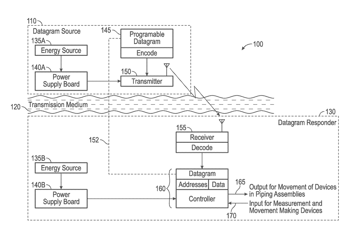
[0076]More specifically, for downhole well completion, one example of how the control system with addressed datagrams would operate is as follows;

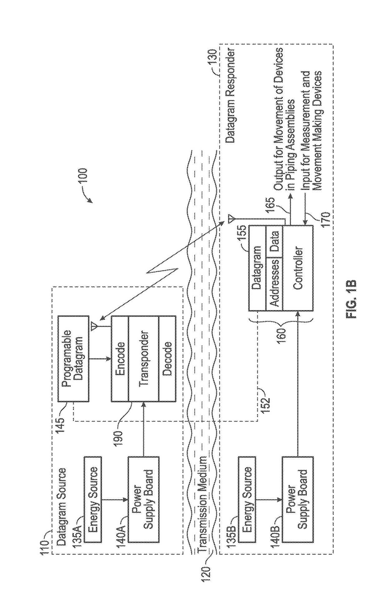
[0077]A user would either send a set of programmed instructions to a controller or utilize a probe with a set of instructions downhole into the wellbore via a transmitter and / or transponder. The set of instructions, in this case, would be to open or close a well completion valve or set of well completion valves located at a specific address within the production tubing or casing. Energy pulses are formed by changes in pressures controlled within the tubing that is accomplished by using a pressure responsive member (such as a piston or a pilot valve) which is adapted to be shifted from one position to another position. The pressure responsive surface located near or on the valve is supplied by the working medium (within the wellbore) to the responsive surface at a pressure substantially equal to the hydrostatic pressure of the wellbore flui...


PUM


Abstract

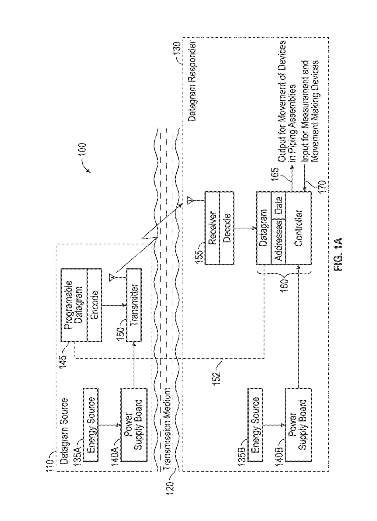
A control system for generating and utilizing at least one or more addressed datagrams that communicate information to and from devices along piping assemblies comprising; one or more transmitters, one or more receivers, and one or more controllers, wherein the transmitters transmit information via one or more addressed datagrams encoded within a working medium to one or more receivers among the piping assemblies, is described. Transmitters convert datagrams into signals that are transmitted within the working medium and the receivers receive signals from the transmitters and also convert signals from the working medium which is converted back into datagrams. The controllers receive and decode the datagrams so that the controllers selectively communicate and perform logical operations on piping assembly devices according to directions received from the addressed datagrams. The entire control system can function as a network of controllers, receivers, transmitters, and / or transponders as required by one or more users.

Description

PRIORITY[0001]This application claims priority under 35 USC 119 from Provisional Application No. 62 / 017,030 entitled “Piping Assembly System with Addressed Datagrams” filed Jun. 25, 2014.FIELD OF INVENTION[0002]This invention relates generally to methods and apparatus for controlling the operation of piping assemblies. More specifically, the invention describes a new and improved downhole tool control system that responds to one or more addressable dynamic datagrams that comprise at least data and signals. A set of transceivers, receivers, and / or transponders transmit, receive, encode and decode one or more of the addressed datagrams so that controllers can selectively communicate and perform logical operations on devices used on piping assemblies according to directions received from the addressed datagrams.BACKGROUND[0003]Systems for controlling piping systems in general, and more specifically for controlling downhole petroleum based well operations have become common practice. Re...

Claims


Application Information

Patent Timeline
IPC IPC(8): E21B47/12E21B34/06E21B34/16G05B19/042G05B15/02H04B1/38G05D7/06
CPCE21B47/12E21B34/06E21B34/16H04B1/38G05B19/042G05D7/0629G05D7/0635G05B15/02Y02P90/02
Inventor LERNER, DANIEL MAURICEORBAN, ANDRE
Owner AOI ADVANCED OILFIELD INNOVATIONS
Learn More