
Powertrain control system

a technology of powertrain and control system, applied in the direction of electric control, ignition automatic control, machines/engines, etc., can solve the problems of increasing costs, increasing exercise time, and affecting so as to improve the efficiency of the engine, increase the number of actuators, and improve the effect of engine efficiency

Active Publication Date: 2018-01-23
FORD GLOBAL TECH LLC
View PDF7 Cites 1 Cited by
  • Summary
  • Abstract
  • Description
  • Claims
  • Application Information

AI Technical Summary

Benefits of technology

[0002]Government regulations on fuel economy and emission standards have driven the development of engine technologies that improve engine efficiency. This technology is enabled by an increased number of actuators and more sophisticated control algorithms. As a consequence, powertrain controls steady-state optimization has increased significantly. The steady state optimization may include examining each speed-load point to determine actuator combination settings that meet predefined constraints and optimizes for fuel economy. However, identifying actuator combinations for each speed-load point may be a complex and lengthy process. As an example, extensive dynamometer data collection and post processing may be required to generate actuator settings for each speed-load point. Overall, this exercise can be prolonged, complicated, and can lead to increased costs.
[0006]In this way, powertrain controls may be optimized without extensive data collection in real time operation. By learning adaptive actuator settings only at selected regions, e.g. at the boundaries of the speed-load map, each speed-load point on the map may not be explicitly visited for gathering data. Therefore, a significant reduction in data collection and post processing may be achieved. Further, since the modeled actuator settings for points within the boundaries of the speed-load map are based on adaptively learned settings for optimized outputs, an improvement in fuel economy and emissions may be attained. Overall, the model may enable a reduction in processing time and an improvement in fuel efficiency.

Problems solved by technology

However, identifying actuator combinations for each speed-load point may be a complex and lengthy process.
Overall, this exercise can be prolonged, complicated, and can lead to increased costs.

Method used


Image

  • Powertrain control system
  • Powertrain control system
  • Powertrain control system

Examples


Embodiment Construction

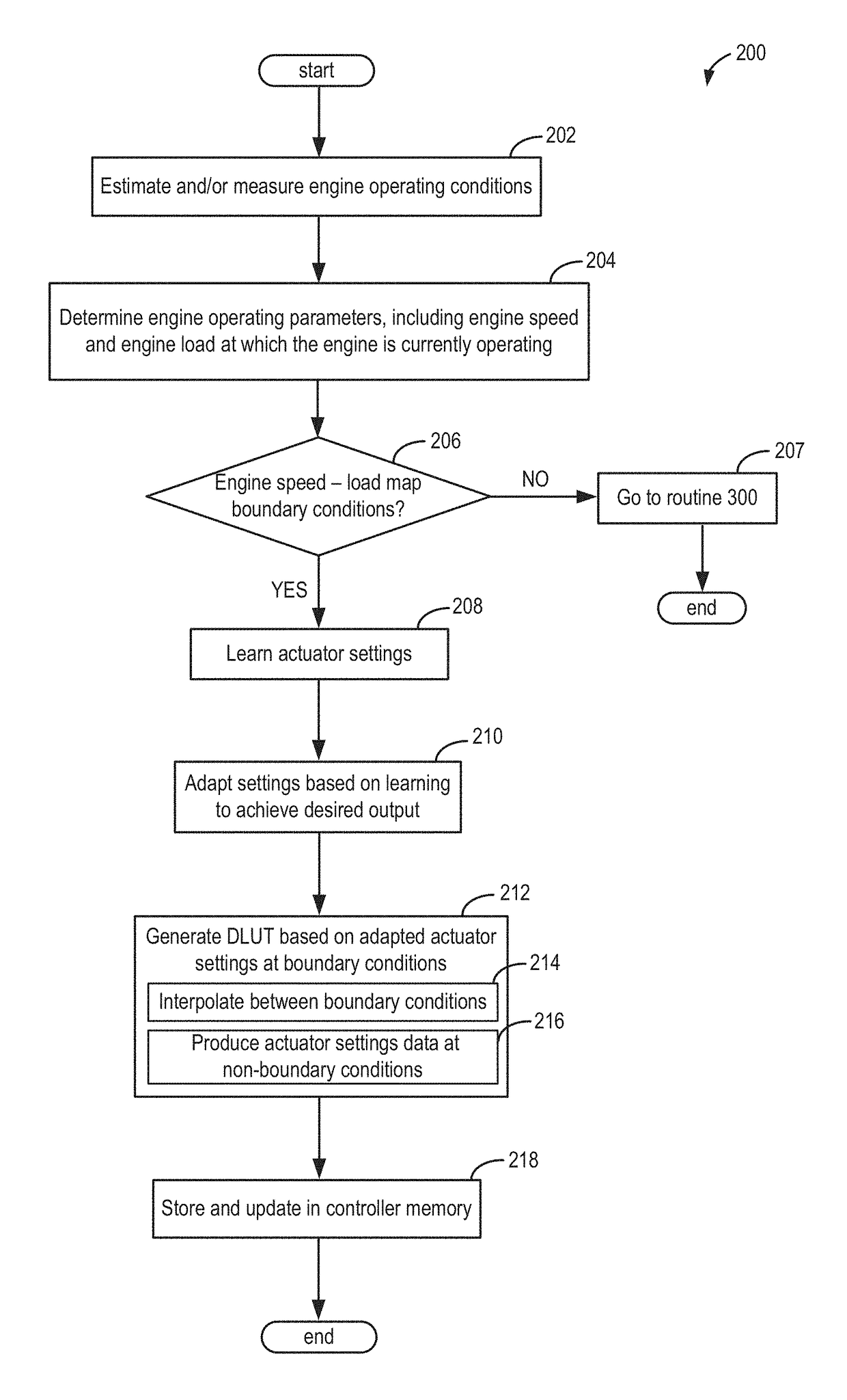
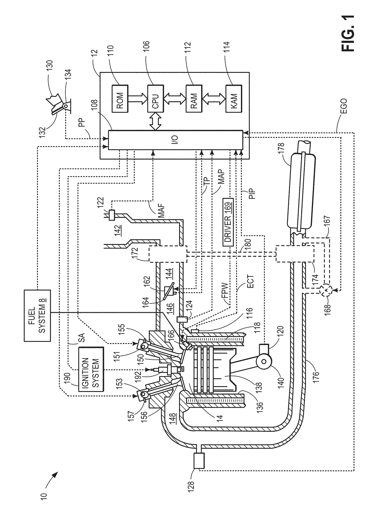
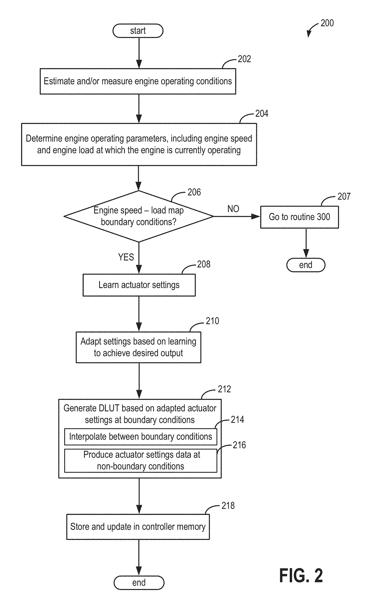
[0017]The following description relates to a method for learning actuator settings in an engine system, such as the engine system of FIG. 1. Actuator settings may be learned and adapted when the engine operates at boundary conditions of an engine speed-load map (FIG. 2). A dynamic node look-up table (DLUT) may be generated via an engine model in parallel to the adaptive learning of actuator settings. The DLUT may include generating actuator settings for engine conditions other than speed-load boundary conditions. Accordingly, when non-boundary conditions arise during real time engine operation, actuator settings may be determined from the DLUT (FIG. 3). In an example described in the present disclosure, an indirect adaptive control system (FIG. 4) may be used to command a selected group of conditions on the speed-load map, specifically, engine loads at the boundary of the speed-load map (FIG. 6). Actuator settings (FIG. 5) that provide the desired outputs of engine load may also be ...


PUM


Abstract

Systems and methods are described for powertrain controls optimization. One method comprises adaptively learning engine settings for a sparse sample of a speed-load map, which includes engine operation at boundary conditions of a speed-load map, and generating a dynamic node look-up table based on the learned engine settings for the sparse sample. The dynamic node look-up table may provide engine settings for engine operation at speed-load points not explicitly learned during the adaptive learning.

Description

CROSS REFERENCE TO RELATED APPLICATIONS[0001]The present application claims priority to U.S. Provisional Patent Application No. 61 / 883,914, “POWERTRAIN CONTROL SYSTEM”, filed on Sep. 27, 2013, the entire contents of which are hereby incorporated by reference for all purposes.BACKGROUND AND SUMMARY[0002]Government regulations on fuel economy and emission standards have driven the development of engine technologies that improve engine efficiency. This technology is enabled by an increased number of actuators and more sophisticated control algorithms. As a consequence, powertrain controls steady-state optimization has increased significantly. The steady state optimization may include examining each speed-load point to determine actuator combination settings that meet predefined constraints and optimizes for fuel economy. However, identifying actuator combinations for each speed-load point may be a complex and lengthy process. As an example, extensive dynamometer data collection and pos...

Claims


Application Information

Patent Timeline
Patent Type & Authority Patents(United States)
IPC IPC(8): F02D41/04F02D41/14F02D41/24F02D28/00F02D41/00F02D35/02F02P5/15
CPCF02D28/00F02D41/1402F02D41/2416F02D41/2441F02P5/151F02D41/0002F02D41/2464F02D2041/001F02D2041/1434F02D35/028
Inventor D'AMATO, ANTHONY MARIOFILEV, DIMITAR PETROVWANG, YAN
Owner FORD GLOBAL TECH LLC
Learn More