Anti-vibration wheel for automobile

a technology for automobiles and wheels, applied in the direction of spoked wheels, mechanical devices, transportation and packaging, etc., can solve the problems of increasing unnecessary stiffness rather than the minimum required strength, increasing weight, and increasing vibration and noise of wheels, so as to reduce vibration and noise, improve riding comfort, and reduce the amount of deformation

Active Publication Date: 2018-01-09
GT C&T CORP
View PDF13 Cites 2 Cited by
  • Summary
  • Abstract
  • Description
  • Claims
  • Application Information

AI Technical Summary

Benefits of technology

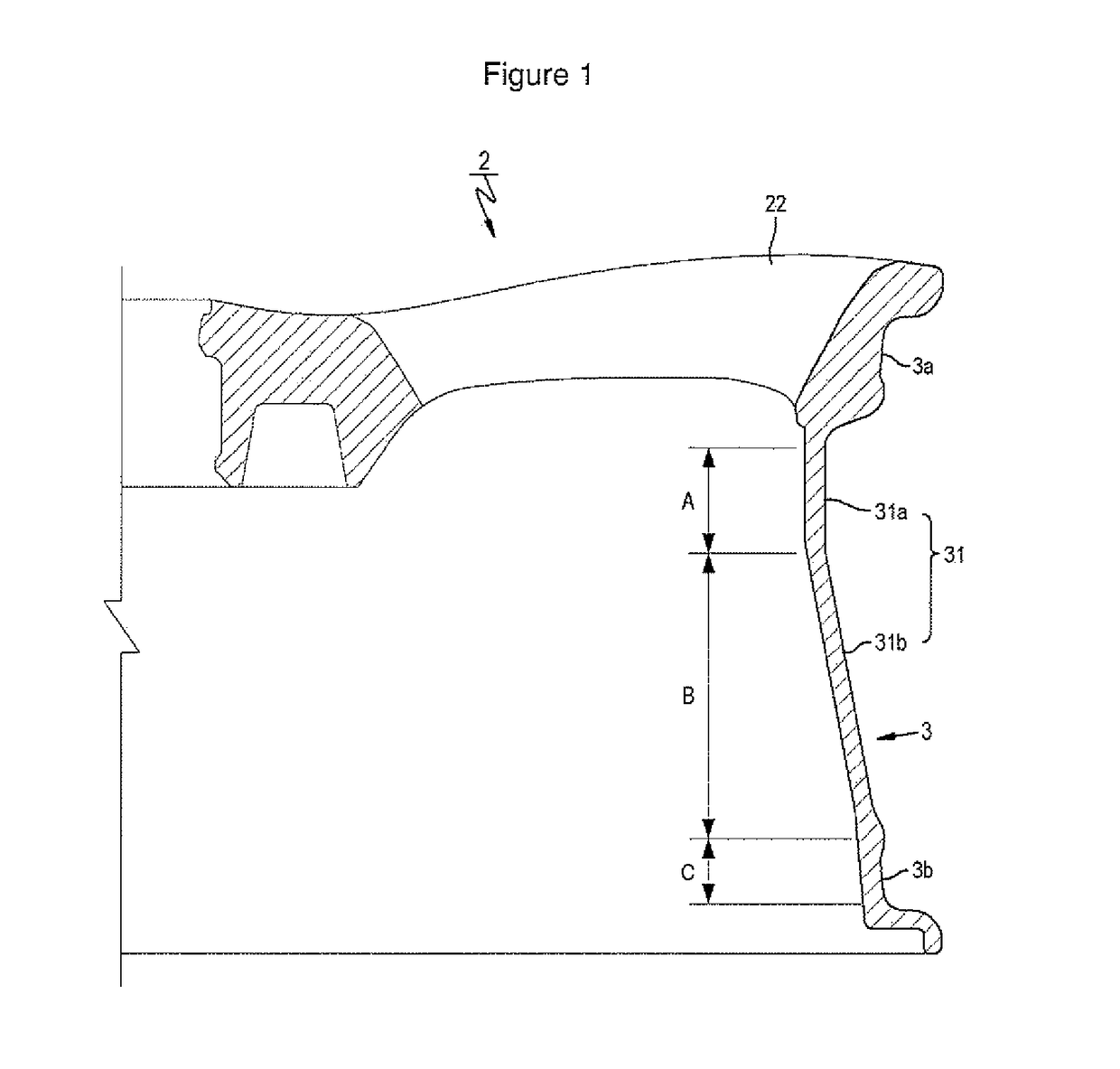
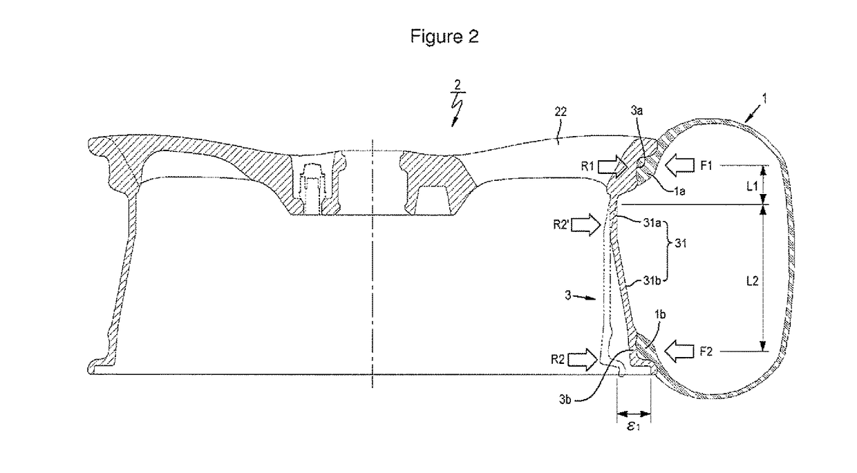
[0031]According to the anti-vibration wheel for an automobile, the well portion and inner bead seat of the rim member are structured to be different from each other in thickness and the inner well portion of the rim member is formed to be inclined at two positions, to minimize the amount of deformation of the well portion and the inner bead seat and therefore to decrease the vibration and noise transferred to the automobile, to improve the riding comfort.
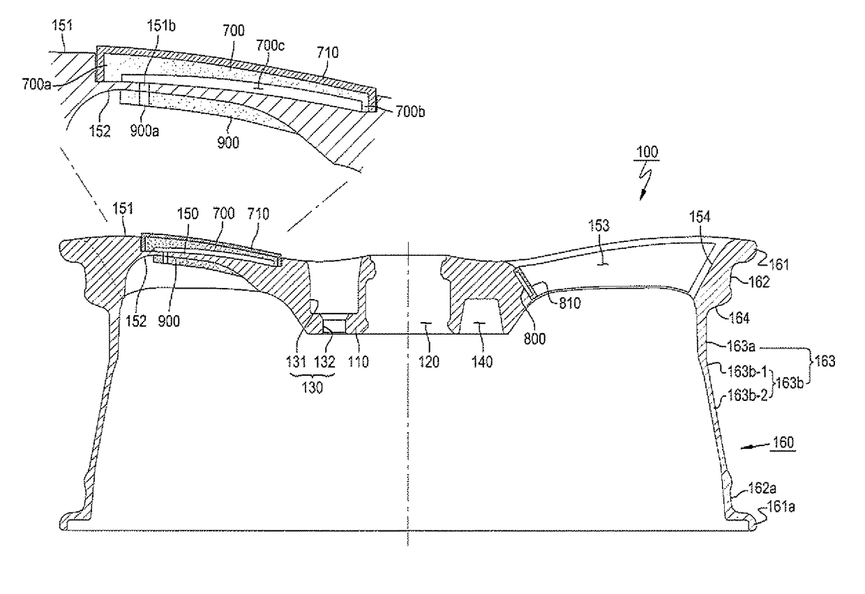
[0032]Further, according to the anti-vibration wheel for an automobile, the vibration damping unit is included in the spoke portion of the wheel, to attenuate vibration and noise transferred to the automobile body through the wheel and to lighten the weight of the wheel itself.

Problems solved by technology

However, as the wheel weight has been lightened through the aforementioned ways, the stiffness becomes insufficient, causing vibration and noise of the wheel during the driving of the automobile.
Even the entire shape of the wheel is thickened, thereby increasing the unnecessary stiffness rather than the minimum required strength.
This again increases the weight and therefore, it restricts the improvement of fuel-efficiency.
The method of forming the hollow chamber has the effect of reducing weight and absorbing noise but it has a problem in that durability is weakened.

Method used


Image

  • Anti-vibration wheel for automobile
  • Anti-vibration wheel for automobile
  • Anti-vibration wheel for automobile

Examples


Embodiment Construction

[0041]The present invention will now be described more fully hereinafter with reference to the accompanying drawings, in which the preferred embodiment(s) of the invention is shown so that those of ordinary skill in the art can easily carry out the present invention.

[0042]The terms used herein are defined in consideration of the function(s) in the present invention and therefore, these terms may vary according to the intention or practice of a user or an operator. Accordingly, the definition of these terms shall be interpreted as having their meaning and concept in the context of the technical detail to work the invention rather than the simple names of the terms.

[0043]Further, the embodiments of the present invention do not limit the scope of the present invention but are just examples of the constituent elements described in the claims of the present invention. Accordingly, the embodiments including alternative constituent elements which are included in the technical idea througho...


PUM


Abstract

There is provided an anti-vibration wheel for an automobile, comprising: a disk member connected to an axle hub with a rim member extending from a circumferential edge of the disk member for mounting a tire, the rim member further having: an outer bead seat positioned at an outer end of the rim member where an outer bead of the tire sits, an inner bead seat positioned at an inner end of the rim member where an inner bead of the tire sits, and a well portion which is inclined and extends between the outer bead seat and the inner bead seat, with an outer well portion extending from the outer bead seat and an inner well portion extending from the outer well portion, with the thickness of the outer well portion being greater than the thickness of the inner bead seat which is greater than the thickness of the inner well portion.

Description

CROSS-REFERENCE TO RELATED APPLICATION[0001]This application claims the benefit of Korean Patent Application No. 10-2015-0145842, filed on 20 Oct. 2015, the disclosure of which is hereby incorporated herein by reference in its entirety.BACKGROUND OF THE INVENTION[0002]Field of the Invention[0003]The present invention relates to an anti-vibration wheel for an automobile and more particularly, to an anti-vibration wheel for an automobile to improve riding comport by attenuating noise and vibration from the surface of a road during the driving of the automobile.[0004]Description of the Related Art[0005]In general, automobile wheels are made of steel or aluminum. This kind of a wheel is secured to a wheel hub having a brake drum or a brake disc by a round head screw or conical head screw.[0006]To improve the fuel-efficiency of an automobile by decreasing the weight of the automobile, aluminum which is a light material has been used for an automobile wheel. Further, a technology to struc...

Claims


Application Information

Patent Timeline
Patent Type & Authority Patents(United States)
IPC IPC(8): F16F15/12B60B7/00B60B21/02B60B3/00B60B1/06B60B7/04B60B7/08B60B7/06B60B3/02B60B3/10
CPCF16F15/1202B60B1/06B60B3/00B60B7/00B60B7/04B60B7/08B60B21/02B60B7/065B60B2900/133B60B3/02B60B3/10B60B2900/131B60B9/00B60B21/023B60B2900/313
Inventor LIM, CHAE-HONG
Owner GT C&T CORP
Why Eureka
Try Eureka