Air lubrication system and vessel comprising such a system

a lubrication system and air technology, applied in watercraft hull design, hull construction, vessel construction, etc., can solve the problems of reducing the air speed of the compressor, reducing the power of the compressor, requiring relatively high pressure, and reducing the frictional drag. , to achieve the effect of reducing the air speed

Active Publication Date: 2018-01-02
SILVERSTREAM TECH
View PDF9 Cites 2 Cited by
  • Summary
  • Abstract
  • Description
  • Claims
  • Application Information

AI Technical Summary

Benefits of technology

[0013]The wave deflector according to the invention stabilizes the flow inside the cavity. By providing a wave deflector inside the cavity with a relatively long dimension in the cavity length direction, the cavity can be filled with air effectively while the vessel is sailing, e.g. at a speed of 20 knots. In operation, the deflector effectively shields the air-filled cavity from water entry due to waves and roll motions of the vessel, the elongate deflector part keeping the water surface inside the cavity stable during roll motions, such that a stable operation of the cavity is warranted. Also in case the vessel sails without air inside the cavity, the elongate deflector part according to the invention results in an undisturbed water flow at reduced drag. As the deflector plane is covering a substantial part of the cavity, it is effectively shielded from wave entry and the stability of the air-filled cavity is improved.
[0037]The widened air inlet was found to be effective for reducing the air speed at the inlet resulting in an undisturbed Kelvin Helmholtz interface and consequent optimal water-air mixing.

Problems solved by technology

The wave deflectors reduce turbulence inside the cavity and cause air to be retained inside the cavity for a longer period of time such that compressors of reduced capacity for less powerful air injection during start up are required.
The known system has as a disadvantage that air injection requires relatively high pressures and is relatively inefficient in view of the power required for lubrication versus reduction in frictional drag.
Furthermore, the wire on the outside of the hull is relatively vulnerable, produces additional drag and may form a point of attachment for dirt, shellfish or seaweed.
Inside the cavity, a lower front part results in an uneven and turbulent air-water interface causing mixing of water and air.
The known lubrication system is relatively inefficient as it operates at non-controlled under-pressures created inside the cavity, and fails to form a flat air-water interface that is level with the flat bottom, allowing mixing of air and water by the Kelvin Helmholtz effect along said whole interface and unrestricted exit from the cavity along the interface onto the bottom in a well-defined and undisturbed boundary layer.

Method used


Image

  • Air lubrication system and vessel comprising such a system
  • Air lubrication system and vessel comprising such a system
  • Air lubrication system and vessel comprising such a system

Examples


Embodiment Construction

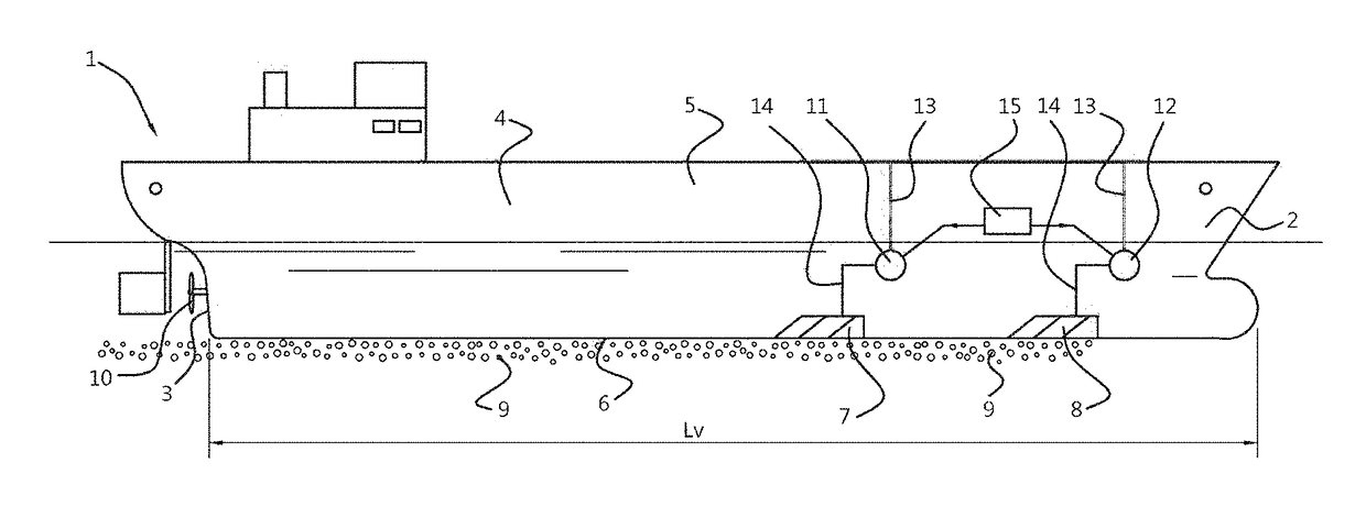
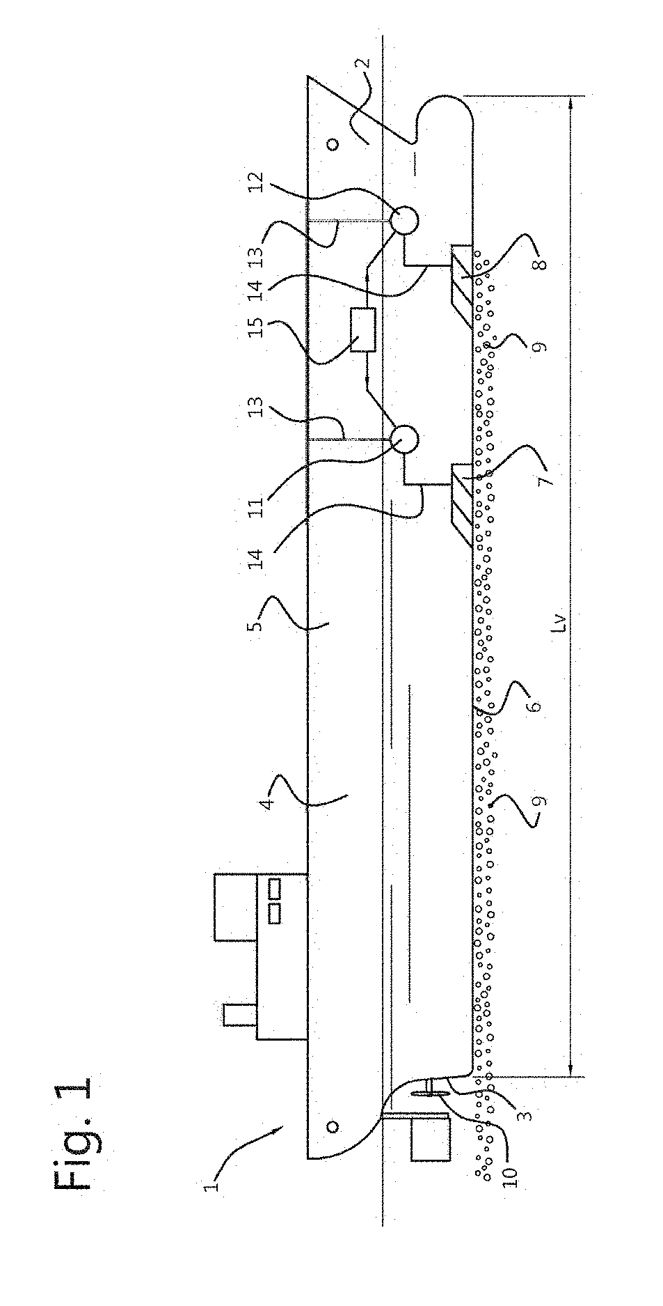
[0047]FIG. 1 shows a vessel 1 having a length Lv of between 20 m and 500 m, and a width between 5 m and 75 m. The vessel 1 may have a water displacement of at least 10000 ton, preferably at least 50000 ton and is an ocean going vessel. The vessel 1 has a hull 4 with a bow 2, a stern 3, sides 5 a substantially flat bottom 6 and a propeller 10. Air lubricating cavities 7,8 that are open in the plane of the bottom 6, are distributed along the bottom 6 to generate a layer of bubbles 9 travelling towards the stern 3, along the flat bottom 6. Compressors 11,12 are connected to each cavity 7,8 for supplying air at the hydrostatic pressure inside each cavity at the prevailing draught level of the vessel. The compressors 11,12 are with an air outlet duct 14 connected to the cavities 7,8 and have an air inlet duct 13 for taking in ambient air. The compressors 11,12 are controlled by a controller 15, for regulating the air supply in dependence of the sailing speed, sea state and during startin...


PUM


Abstract

A system (16) for providing an air lubricating layer between a substantially flat bottom (6) of the hull (4) of a vessel (1) and water flowing under the bottom as the vessel is moving through the water. The system has a cavity (33) with a deflector. The deflector has an elongate part (29,34,34′) extending in the length direction of the cavity over at least at least 5%, preferably at least 10% of the cavity length L, wherein a projected area of the at least one deflector member (24,24′-26,26′) on the interface plane (30) covers at least 25%, preferably at least 50%, most preferably at least 75% of the surface area of the interface plane.

Description

FIELD OF THE INVENTION[0001]The invention relates to a system for providing an air lubricating layer between a substantially flat bottom of the hull of a vessel and water flowing under the bottom as the vessel is moving through the water, which system comprises sidewalls and a top wall defining a cavity with an opening situated in an interface plane that is transversely to the sidewalls, substantially at the level of the flat bottom, the opening having a front end and a rear end when seen in the length direction of the cavity, an air inlet spaced from the opening of the cavity, the cavity having a length Lc, a distance of the top wall from the interface plane Hc and a width W, wherein the ratio Lc / Hc is within the range of 7:1 to 13:1, the ratio W / H is in the range of 1.3:1 to 2.5:1 and the ratio Lc / W is in the range of 3.5 to 1 to 7:1, at least one water deflector being provided in the cavity, the deflector extending substantially across the width of the cavity and having a lower e...

Claims


Application Information

Patent Timeline
Patent Type & Authority Patents(United States)
IPC IPC(8): B63B1/38
CPCB63B1/38Y02T70/122B63B2001/387Y02T70/10
Inventor JOHANNNESSON, JOHANNESSILBERSCHMIDT, NOAHCLAUSEN, JORGEN
Owner SILVERSTREAM TECH
Why Eureka
Try Eureka