
Dental bracket

a technology for teeth and brackets, applied in the field of dental brackets, can solve the problems of dental deviation, malposition of teeth, and diminishing aesthetic appeal, and achieve the effect of reducing the chance of tooth decay and the foreign body sensation in the mouth

Active Publication Date: 2017-12-19
WU CHUAN CHUNG
View PDF24 Cites 14 Cited by
  • Summary
  • Abstract
  • Description
  • Claims
  • Application Information

AI Technical Summary

Benefits of technology

The present invention is a dental bracket that reduces the chance of tooth decay and the foreign body sensation in the mouth. The dental bracket has a base and an engaging unit. The engaging unit has a plate, two engaging arms, and a blocking protrusion. The engaging arms are connected to the base and form a space between them. The blocking protrusion divides the space into two channels for inserting an archwire. The dental bracket reduces the foreign body sensation in the mouth and is comfortable to wear.

Problems solved by technology

The malposition of teeth, also known as dental deviation, is often caused by excessive or inadequate space for teeth growth.
The malposition of teeth not only diminishes the aesthetic appeal in the look of the patient, but also causes malocclusion and brings forth a negative effect on chewing.
However, the elastomeric ligature is difficult to be mounted on and around the bracket body in the oral cavity.
Although the conventional self-ligating brace is easier than the traditional orthodontics bracket in assembly, the uneven outline of the brace body makes food debris easily stuck to the brace body, causes the brace body hard to be cleaned, and raises the chance of tooth decay.
And more particularly, the uneven outline of the brace body continually rubs the interior of the mouth and causes a foreign body sensation in the mouth.

Method used


Image

  • Dental bracket
  • Dental bracket
  • Dental bracket

Examples


Embodiment Construction

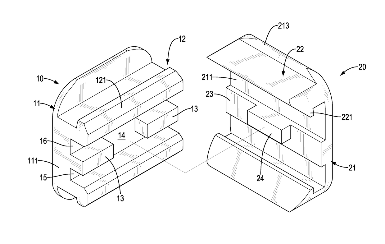
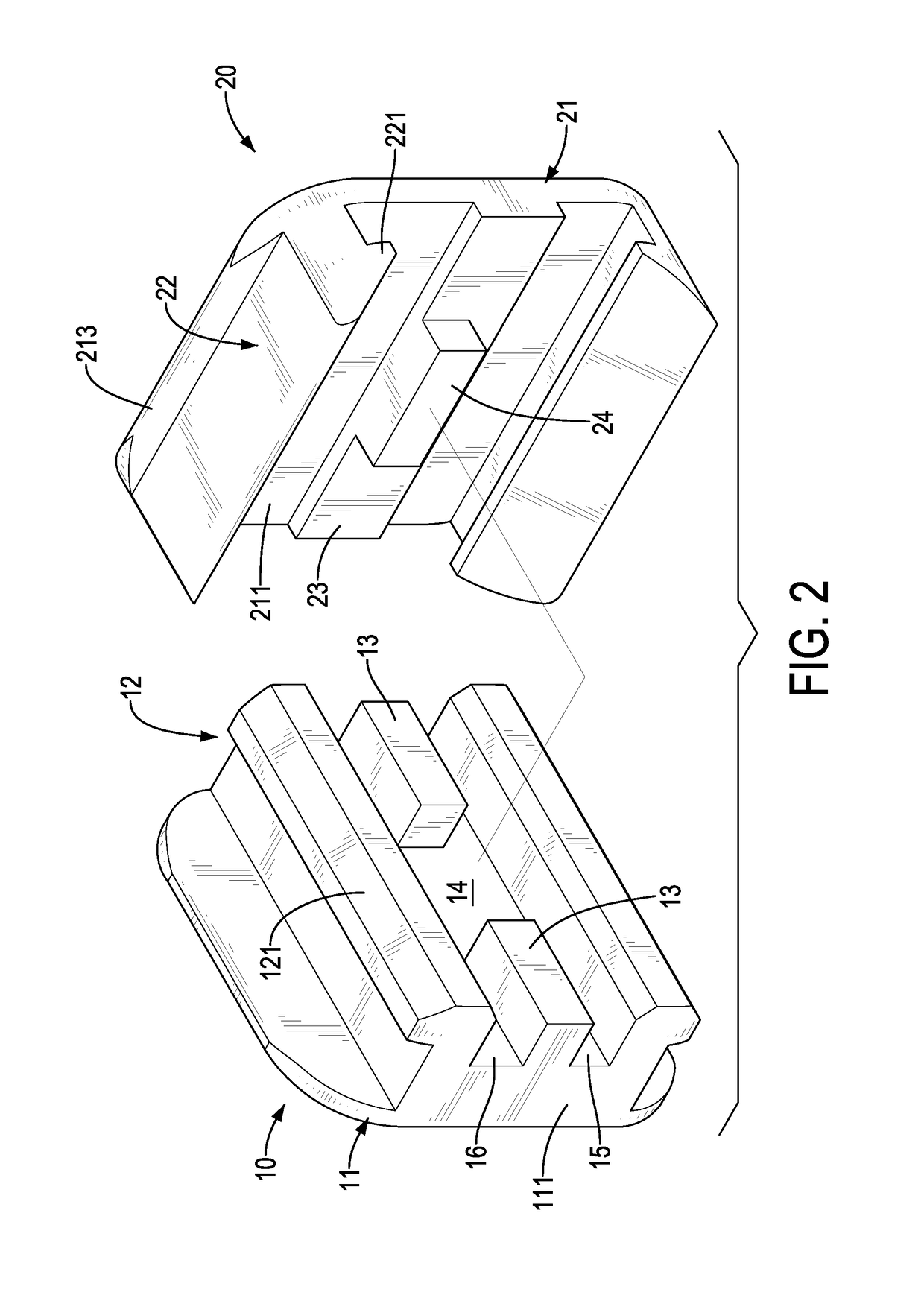
[0015]With reference to FIGS. 1 and 2, a dental bracket in accordance with the present invention comprises a base 10 and an engaging unit 20. The engaging unit 20 is mounted on the base 10.

[0016]With reference to FIGS. 2 and 3, the base 10 has a longitudinal direction, a basal plate 11, two engaged protrusions 12, two limiting protrusions 13, and a gap 14. The basal plate 11 is rectangular and has a surface and two ends 111. The two ends 111 of the basal plate 11 are opposite each other in the longitudinal direction of the base 10. The two engaged protrusions 12 are spaced from each other, are formed on the surface of the basal plate 11, and extend along the longitudinal direction of the base 10. Each engaged protrusion 12 has a hook portion 121 distal from the basal plate 11. The two hook portions 121 of the two engaged protrusions 12 respectively face to two opposite directions. The two limiting protrusions 13 are spaced from each other, are arranged between the two engaged protru...


PUM


Abstract

A dental bracket has a base and an engaging unit. The base has two engaged protrusions and two limiting protrusions. The engaging unit is mounted on the base and forms a space between the base and the engaging unit. The engaging unit has a plate, two engaging arms, and a blocking protrusion. The plate has a first surface and a second surface being flat and opposite the first surface. The two engaging arms are formed on the first surface of the plate and respectively engaged with the two engaged protrusions of the base. The blocking protrusion is formed on the first surface of the plate, is arranged between the two limiting protrusions of the base, and divides the space into two channels for inserting an archwire. The second surface of the engaging unit is flat and is able to decrease the foreign body sensation in the mouth.

Description

BACKGROUND OF THE INVENTION1. Field of the Invention[0001]The present invention relates to an apparatus for orthodontics, and more particularly to a dental bracket with a smooth structure that can reduce the chance of tooth decay and the foreign body sensation in the mouth.2. Description of Related Art[0002]The malposition of teeth, also known as dental deviation, is often caused by excessive or inadequate space for teeth growth. The malposition of teeth not only diminishes the aesthetic appeal in the look of the patient, but also causes malocclusion and brings forth a negative effect on chewing.[0003]There are many types of dental brackets used to correct the malposition of teeth. The traditional orthodontics bracket has a bracket body, an archwire, and an elastomeric ligature. The bracket body is glued on a tooth. The archwire is assembled into the bracket body. The elastomeric ligature is mounted on and around the bracket body to fix the archwire. The interaction between the brac...

Claims


Application Information

Patent Timeline
IPC IPC(8): A61C3/00A61C7/12A61C7/28A44C15/00
CPCA61C7/125A61C7/287A44C15/007A61C7/143A61C7/28
Inventor WU, CHUAN-CHUNG
Owner WU CHUAN CHUNG
Learn More