
Constrained joint protector

a protector and joint technology, applied in the field of hand protection guards, can solve the problems of incomplete protection, hand injury, and hand close proximity, and achieve the effects of increasing the degree of extension, and reducing the risk of injury

Active Publication Date: 2017-12-12
WULF COREY
View PDF8 Cites 1 Cited by
  • Summary
  • Abstract
  • Description
  • Claims
  • Application Information

AI Technical Summary

Benefits of technology

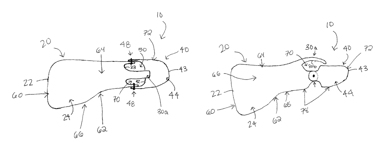
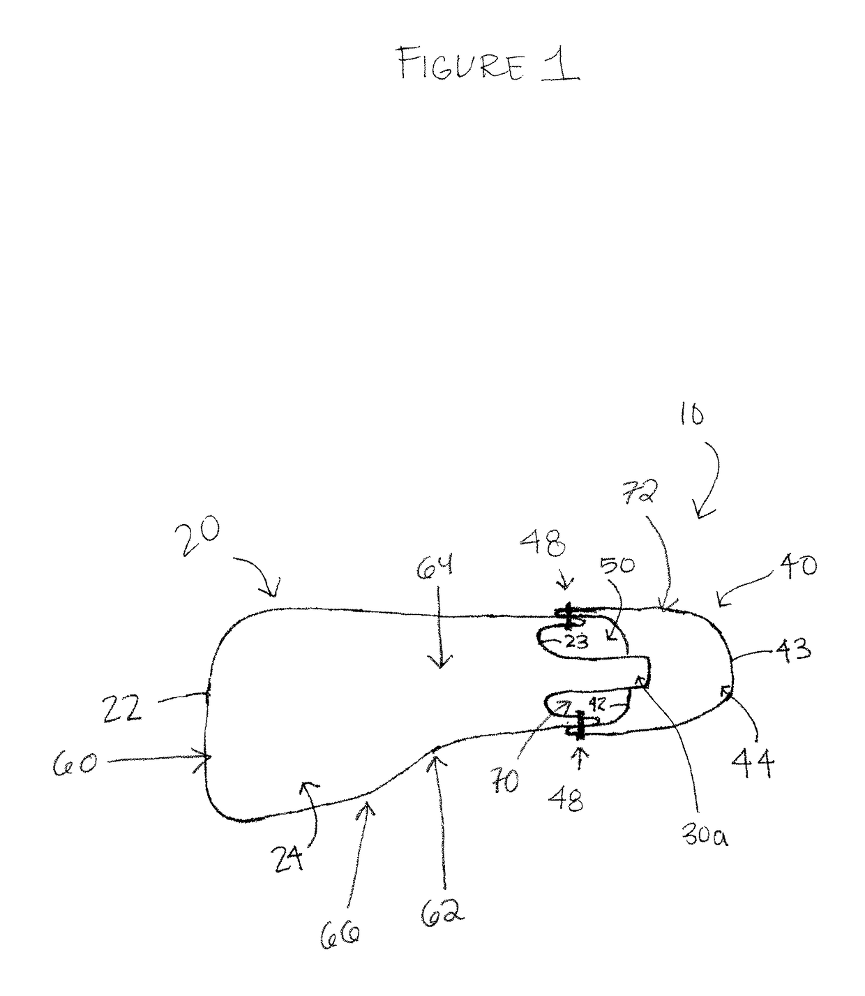
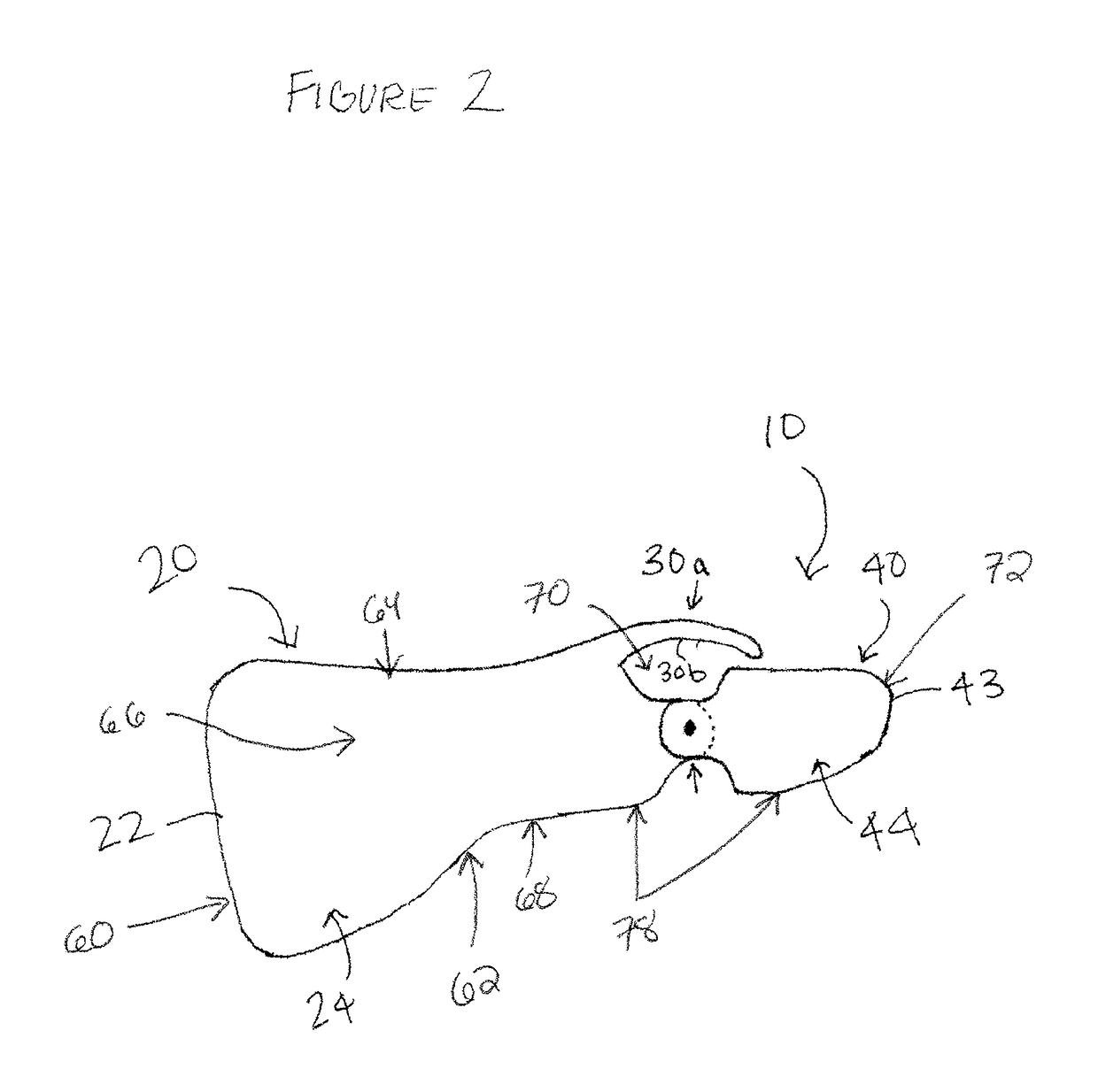
[0006]The protective guard of the present invention incorporates static or fixed positioning of the metacarpal, proximal phalanx, and metacarpophalangeal joint of a ray of the hand with a linked, articulated distal phalanx protective portion which allows for full functional flexion and limited extension of the inter-phalangeal joint. Protected flexion and extension of the inter-phalangeal joint may be accomplished by a curved dorsal extension from the metacarpal / proximal phalanx protective element that abuts the distal phalanx protective element as the inter-phalangeal joint increases the degrees of extension from a neutral position. The curved dorsal extension from the metacarpal / proximal phalanx protective element also provides protection from direct impact over the dorsal interphalangeal joint when it is in the flexed position. Finally, the current design is to be worn inside a standard protective glove or alone.

Problems solved by technology

These designs prevent close proximity of the protective apparatus to the hand and incomplete protection due to increased clearance between the thumb and rigid protective element.
This leaves the thumb vulnerable to injuries from direct impact on the volar surface, especially the volar aspect of the distal phalanx when the thumb is in an extended position.
It does so in a rigid manner and does not allow any physiologic movement of the thumb.
This fails to account for ligamentous injuries to the articular joints in all directions both physiologic and non-physiologic.

Method used


Image

  • Constrained joint protector
  • Constrained joint protector
  • Constrained joint protector

Examples


Embodiment Construction

[0014]The present disclosure relates to novel and advantageous protective guards for hand rays, i.e. the thumb or fingers. More particularly, the present disclosure relates to novel and advantageous protective guards that allow sufficient physiological movement of the ray, while preventing injury, or further injury, to the ray or ligaments.

[0015]FIGS. 1-4 show one embodiment of the inventive protective guard 10 disclosed herein. The inventive protective guard may be constructed for protection of a ray on one or both of the right or left hand. In at least the embodiment shown in FIGS. 1-4, the inventive protective guard 10 is constructed for use with the first ray (i.e. thumb) of the right hand, although the device may be used with any ray (i.e. thumb or finger). As shown in FIGS. 1-4, the protective guard 10 comprises a first body 20 and a second body 40. First body 20 and second body 40 may be constructed of metal, plastic, polymer or any combination of such materials. Desirably, f...


PUM


Abstract

A protective guard for protecting a body joint, the protective guard comprising: a first body having a first end and a second end; a second body having a first end and a second end, the second body rotatably connected to the first body at the second end of the first body, the first body and the second body defining an opening therebetween; and an extension member that extends distally from the first body towards the second body across the opening, wherein the extension member has a curvilinear profile with an apex aligned with the body joint. The extension member allows movement of the body joint while protecting the joint from direct impact.

Description

CROSS-REFERENCE TO RELATED APPLICATIONS[0001]This application claims priority to provisional application 61 / 924,616 entitled “Constrained Thumb Protector,” filed Jan. 7, 2014, which is hereby incorporated herein in its entirety.FIELD OF THE INVENTION[0002]The present invention relates to protective guards for the hand for use during activities, such as athletic activities, which may create a risk of damage or injury, and in some cases further injury, to one or more rays of the hand.DESCRIPTION OF THE RELATED ART[0003]Protective guards of the prior art typically describe devices that attach externally to a protective glove (for example, U.S. Pat. No. 8,181,275 to Saturnio; US Pat. Pub. No. 2012 / 0284892 to Szurley et al; U.S. Pat. No. 7,784,110 to Jourde et al, which are hereby incorporated herein in their entireties), but fail to conform anatomically to the thumb. These designs prevent close proximity of the protective apparatus to the hand and incomplete protection due to increased ...

Claims


Application Information

Patent Timeline
Patent Type & Authority Patents(United States)
IPC IPC(8): A41D13/08
CPCA41D13/087A41D13/081
Inventor WULF, COREY
Owner WULF COREY
Learn More