
Vehicular control device

a technology of vehicle control and control device, which is applied in the direction of anti-theft devices, instruments, vehicle components, etc., can solve the problem of delay in the time at which the following unauthorized access can be performed, and achieve the effect of avoiding the prohibition of vehicle operation

Active Publication Date: 2017-12-05
TOYOTA JIDOSHA KK
View PDF8 Cites 4 Cited by
  • Summary
  • Abstract
  • Description
  • Claims
  • Application Information

AI Technical Summary

Benefits of technology

The present invention relates to a vehicular control device that can prevent a vehicle from being stolen by prohibiting its operation based on abnormal communication with an electronic key. The device determines whether an abnormal state has occurred by checking if a response signal is received and verifying the electronic key. The device also specifies the time period when the vehicle operation is prohibited to avoid cancelling the prohibition and encouraging unauthorized access. Overall, the device ensures that the vehicle operation is safe and prevents it from being stolen.

Problems solved by technology

Thus, in a case where, for example, unauthorized access to the vehicle is performed, and abnormality in communication occurs, a time at which the following unauthorized access can be performed can be delayed.

Method used


Image

  • Vehicular control device
  • Vehicular control device
  • Vehicular control device

Examples


first specific example

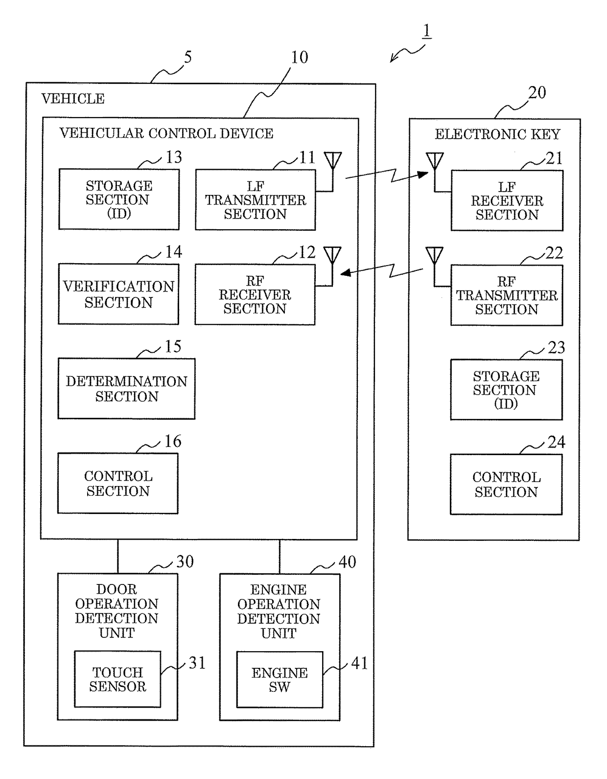
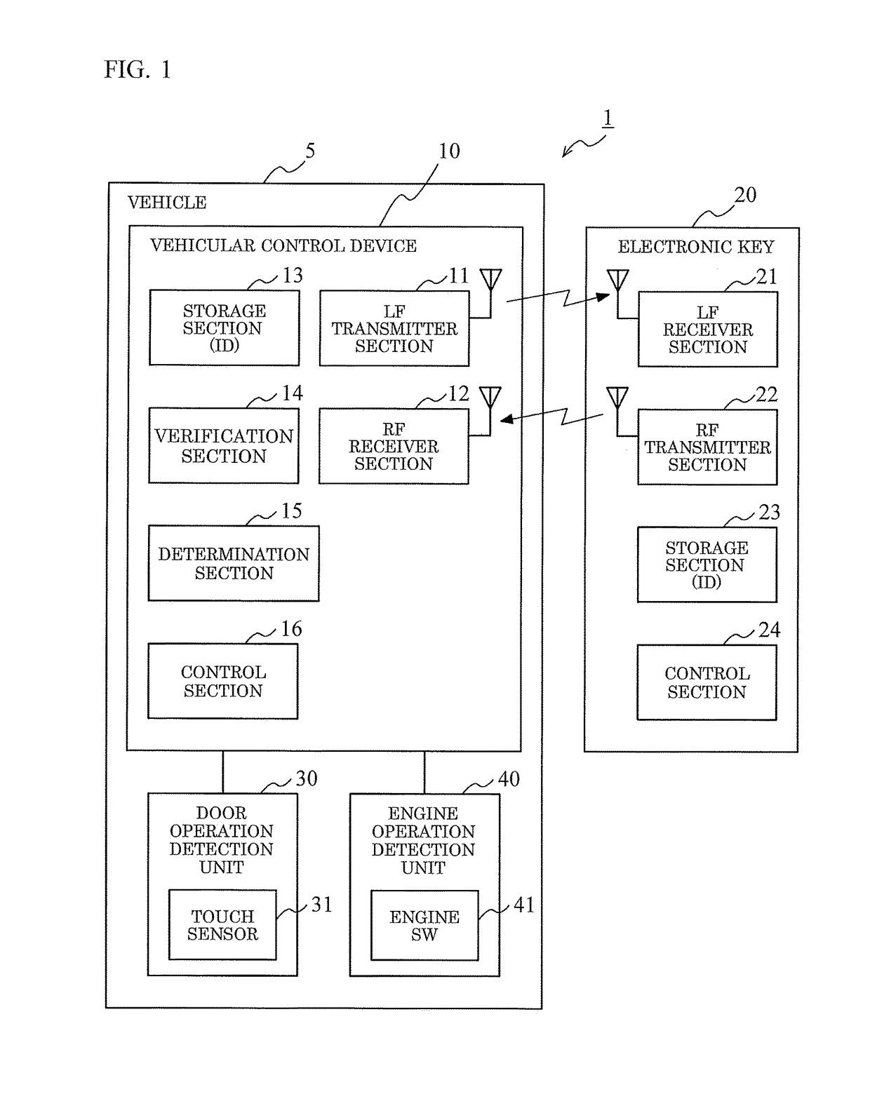
[0048]FIG. 3 is a flow chart showing process steps, of a first specific example, performed by the vehicular control device 10 according to one embodiment of the present invention. In the first specific example shown in FIG. 3, a case where the vehicle 5 in which the vehicle door is locked, is instructed to unlock the door by an action of “touching the touch sensor 31 mounted at a door handle” being performed as a predetermined input operation, is assumed.

[0049]Firstly, the counted value N is reset and initialized (step S301). After the counted value N is reset and initialized, the control section 16 determines whether or not a predetermined detection section detects an input operation onto the vehicle (step S302). In the first specific example, for example, the control section 16 determines whether or not the door operation detection unit 30 detects that the touch sensor 31 mounted at the door handle has been touched.

[0050]When it is detected that the touch sensor 31 has been touche...

second specific example

[0063]FIG. 4 is a flow chart showing process steps, of a second specific example, performed by the vehicular control device 10 according to one embodiment of the present invention. In the second specific example shown in FIG. 4, a case where an instruction is made for staring up an engine by an action of “pressing down an engine SW 41” being performed as a predetermined input operation in a state where a person is in the vehicle 5, is assumed.

[0064]Firstly, the counted value N is reset and initialized (step S401). After the counted value N is reset and initialized, the control section 16 determines whether or not the predetermined detection section detects an input operation onto the vehicle (step S402). In the second specific example, for example, the control section 16 determines whether or not the engine operation detection unit 40 detects that the engine SW 41 mounted at the instrument panel has been pressed.

[0065]When it is detected that the engine SW 41 has been pressed (Yes i...


PUM


Abstract

A vehicular control device includes: a transmitter section that transmits a request signal to an electronic key according to an input operation; a receiver section that receives a response signal from the electronic key; a verification section that performs verification of the electronic key on the basis of the response signal; a determination section that determines that an abnormal state occurs, when the receiver section cannot receive the response signal until a first time or when the receiver section receives the response signal until the first time and the verification section fails in verification based on the response signal, after the transmitter section has transmitted the request signal; and a control section that prohibits, when the determination section determines that an abnormal state occurs, a vehicle operation until a second time passes after the determination, and allows the vehicle operation after the second time has passed.

Description

BACKGROUND OF THE INVENTIONField of the Invention[0001]The present invention relates to vehicular control devices that are mounted to vehicles, and control vehicle operation by performing verification through wireless communication with electronic keys.Description of the Background Art[0002]As one of systems mounted to a vehicle, an electronic key system (also referred to as a wireless key system, a keyless entry system, a smart entry system, or the like) that performs verification through wireless communication between an electronic key which can be carried by a user, and an in-vehicle device mounted in a vehicle, and that controls the vehicle on the basis of the verification result, is known.[0003]In the electronic key system, the in-vehicle device transmits a request signal to the electronic key. When the electronic key receives the request signal from the in-vehicle device, the electronic key returns, to the in-vehicle device, a response signal that includes identification infor...

Claims


Application Information

Patent Timeline
IPC IPC(8): G07C1/32E05B81/04B60R25/01G07C9/00
CPCG07C1/32G07C9/00309G07C9/00658E05B81/04B60R25/01B60R25/241G07C9/00896B60R25/24G07C2009/00769G07C2209/08
Inventor NISHIYAMA, SHIGEKIFUNAYAMA, TOMOYUKI
Owner TOYOTA JIDOSHA KK
Learn More