
Opening and closing apparatus and image forming apparatus

a technology of opening and closing apparatus and opening and closing, which is applied in the direction of instruments, wing accessories, electrographic processes, etc., can solve the problems of slow closing movement, too fast closing velocity, and inability to close fast and accurately

Active Publication Date: 2017-12-05
BROTHER KOGYO KK
View PDF15 Cites 3 Cited by
  • Summary
  • Abstract
  • Description
  • Claims
  • Application Information

AI Technical Summary

Benefits of technology

The present patent aims to provide an opening and closing apparatus that allows for a slow and smooth closure of the openable body. It achieves this by generating a force component in the vicinity of the closed position during the closing movement, which reduces the velocity of the openable body in that area. This results in a slow and gentle closure of the openable body, making it easier to reach the closed position.

Problems solved by technology

Thus, when the rotating damper having a small load is used, although the closing velocity of the openable body is appropriate at the beginning of the closing movement of the openable body from the open position, the closing velocity becomes too fast just before the closed position.
When the rotating dumper having a large load is used, although the closing velocity of the openable body is appropriate just before the closed position, the closing velocity is too slow at the beginning of the closing movement from the open position.
This lengthens the time for closing movement of the openable body, which is unfavorable.
Accordingly, it is very difficult to appropriately control the closing velocity of the openable body only by use of the rotating damper.

Method used


Image

  • Opening and closing apparatus and image forming apparatus
  • Opening and closing apparatus and image forming apparatus
  • Opening and closing apparatus and image forming apparatus

Examples


first modified embodiment

[0089]In the multifunction peripheral 8 of the first modified embodiment, when the image reading unit 3 pivots from the open position to the closed position, the closing velocity of the image reading unit 3 decreases in the vicinity of the closed position, similar to the above embodiment.

[0090]

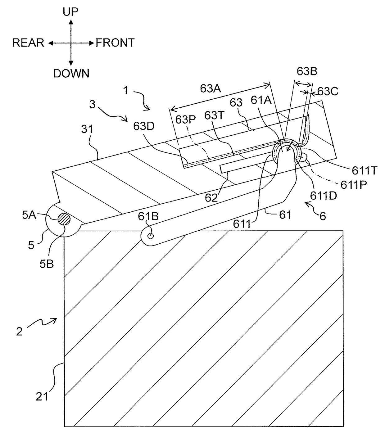
[0091]In the above embodiment, the pitch line 63P of the rack 63 includes the horizontal line 63A. However, the pitch line 63P of the rack 63 may not include the horizontal line 63A. This configuration is regarded as the second modified embodiment, and FIG. 10 depicts a partial sectional side view of a multifunction peripheral 9 according to the second modified embodiment. In FIG. 10, the constitutive parts or components, which are the same as or equivalent to those of the embodiment described above, are designated by the same reference numerals, any explanation of which will be omitted as appropriate.

second modified embodiment

[0092]The multifunction peripheral 9 of the second modified embodiment includes an image forming unit 2, an image reading unit 3, an operation panel (not depicted), a connecting part 5, and an opening and closing mechanism 6. The opening and closing mechanism 6 includes an arm 61, a guide groove 64, and a rack 65.

[0093]The guide groove 64 is formed along a pitch line 65P of the rack 65 below the rack 65 of a casing 31. The guide groove 64 is an elongated hole which slidably supports the rotating shaft of a pinion 611. The guide groove 64 guides the rotating shaft of the pinion 611 when the pinion 611 moves along the rack 65 according to opening and closing of the image reading unit 3.

[0094]The rack 65 is fixed to the casing 31 in a state that each tooth tip faces the image forming unit 2. The rack 65 extends in the front-rear direction orthogonal to the pivot axis. The front end of the rack 65, which is opposite to the connecting part 5, is positioned closer to the front end of the ...


PUM


Abstract

There is provided an opening and closing apparatus, including: a main body; an openable body pivoting between a closed position and an open position; a connecting part connecting an end of the main body and an end of the openable body; a rack provided in one of the main body and the openable body; and an arm, wherein a part, of a pitch line of the rack, which makes contact with a pitch circle of the pinion in a state that the openable body is positioned in the vicinity of the closed position is an inclined line which is inclined to approach the other of the main body and the openable body having no rack, as the inclined line is farther away from the connecting part with the openable body being in the closed position.

Description

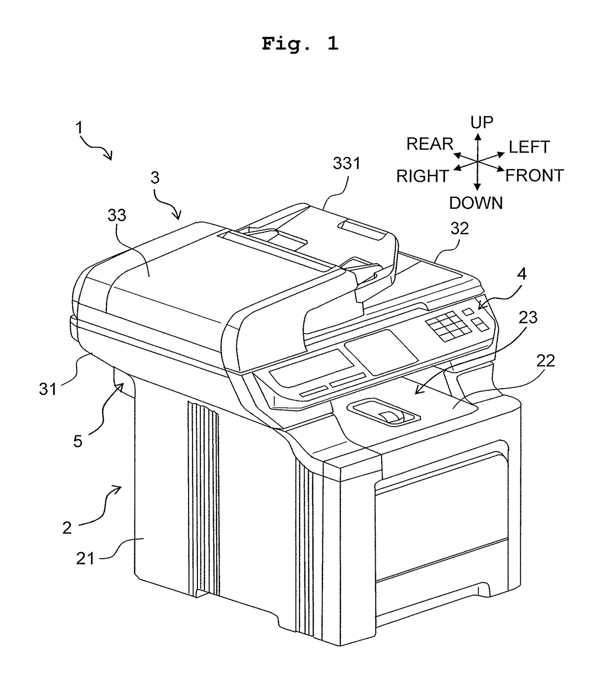
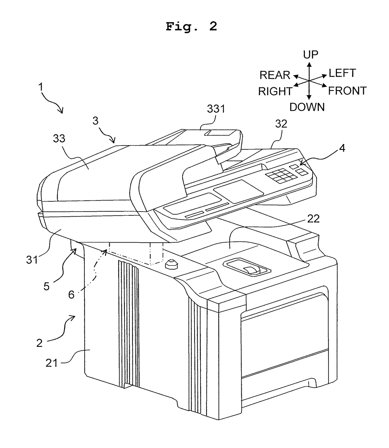
CROSS REFERENCE TO RELATED APPLICATION[0001]The present application claims priority from Japanese Patent Application No. 2015-178011 filed on Sep. 9, 2015, the disclosure of which is incorporated herein by reference in the entirety.BACKGROUND[0002]Field of the Invention[0003]The present invention relates to an opening and closing apparatus configured by pivotably connecting a main body and an openable body (an opening and closing body), and an image forming apparatus provided with the opening and closing apparatus.[0004]Description of the Related Art[0005]There are conventionally known opening and closing apparatuses configured by pivotably connecting a main body and an openable body. Such opening and closing apparatuses are used, for example, in image forming apparatuses such as printers, scanners, and multifunction peripherals.[0006]In some image forming apparatuses, the main body includes an image forming unit and the openable body configured to cover an upper part of the main bo...

Claims


Application Information

Patent Timeline
Patent Type & Authority Patents(United States)
IPC IPC(8): E05F5/02G03G21/16H04N1/00
CPCE05F5/02G03G21/1628G03G21/1633H04N1/00551E05Y2201/21H04N2201/0094E05Y2201/716E05Y2201/722E05Y2900/20G03G2221/1687E05Y2201/266
Inventor TOMATSU, YOSHIYA
Owner BROTHER KOGYO KK
Learn More