Skin patch dosimeter

a dosimeter and patch technology, applied in the field of skin patch dosimeters, can solve the problems of limited use of radiation therapy in non-malignant conditions, potential for cancer, radiation-induced cancer risk, etc., and achieve the effects of not easily disturbed or reshaped, sufficient stiffness, and even or smooth dos

Active Publication Date: 2017-12-05
ANGIODYNAMICS INC
View PDF51 Cites 1 Cited by
  • Summary
  • Abstract
  • Description
  • Claims
  • Application Information

AI Technical Summary

Benefits of technology

[0031]We specifically contemplate a groove herein into which the sensor can fit, but in some embodiments the sensor could fit into a tubular hole for same, although this is less desired as being less easy to assemble. Alternatively, the groove can be covered with another layer, thus providing the easy insertion of the sensor into a groove plus the security of a fully embedded sensor.
[0036]By “bolus” herein, what is meant is a water equivalent material that assists in evening or smoothing the dose provided to the body and / or controlling the depth of the dosage. Preferred bolus materials are moldable, such that they can be shaped by the user, and particularly preferred materials will hold that shape throughout treatment, e.g., by curing, cooling, fixing or simply by having sufficient stiffness so as to not easily be disturbed or reshaped.

Problems solved by technology

The use of radiation therapy in non-malignant conditions is limited partly by worries about the risk of radiation-induced cancers.
Radiation therapy works by damaging the DNA of e.g., cancerous cells, and thus itself has the potential for causing cancers.
This damage is either direct or indirect ionization of the atoms that make up the DNA chain.
Misdirected radiation beams may perforate the rectal wall causing radiation proctitus (rectal bleeding), as well as erectile dysfunction (ED), incontinence and other complications.
However, the risk is not eliminated and organs at risk include the breast and underlying muscle, ribs, lung, and heart.
The irregular shapes make it difficult to plan and administer an optimum radiation dose to the treatment site.
One drawback concerning these detectors is the radiation-induced light arising in the optical fibers, a combination of Cerenkov emission and fluorescence.
These detectors have not yet been accepted into standard clinical practice, because until recently they were not commercially available.
Several skin patch sensors are available, but most are simple sensors attached to an adhesive patch, and many are not capable of real time dosimetry.
Additionally, the system is not real time, requiring the oncologist contact the sensor patch with a dose-reader device after the administering step to obtain data associated with a change in an operational parameter in the dosimeter sensor patch.

Method used


Image

  • Skin patch dosimeter
  • Skin patch dosimeter
  • Skin patch dosimeter

Examples


Embodiment Construction

[0063]The following descriptions and figures are exemplary only and should not be used to unduly limit the scope of the invention.

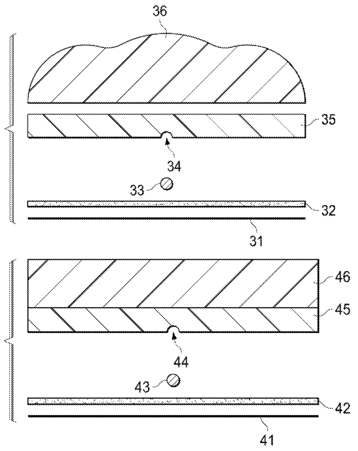
[0064]Current skin sensor patches are made by sandwiching a sensor between two flat layers, and adding adhesive to the bottom surface for temporary attachment to the epidermis. However, such construction always leaves air pockets to each side of the sensor, which interferes with accurate dosing. Further, the larger the sensor, the greater the air gap. This interferes with accurate delivery of radiation, since radiation will travel faster through air.

[0065]The current invention provides a patch with a groove in the bottom surface for receiving the sensor and which eliminates the air pockets. In addition, the groove ensures accurate and reproducible placement of the sensor tip on the patch, thus simplifying manufacture and improving the reliability of the sensor.

[0066]If desired, the sensor can be sealed into the groove, e.g., with an adhesive or with a cov...


PUM


Abstract

A skin patch sensor having a groove therein to receive a sensor without leaving any air pockets is described. The skin patch sensor also has a water or tissue equivalent material and / or, in some embodiments, a moldable water equivalent material.

Description

PRIOR RELATED APPLICATIONS[0001]This application claims priority to 62 / 049,258, filed Sep. 11, 2014. This application also claims continuation-in-part priority to 61 / 481,503, filed May 2, 2011, and Ser. No. 13 / 444,584, filed Apr. 11, 2012, issued as U.S. Pat. No. 8,885,986, and Ser. No. 14 / 470,707, filed Aug. 27, 2014, issued as U.S. Pat. No. 8,953,912. Each is incorporated by reference herein in its entirety for all purposes.FIELD OF THE DISCLOSURE[0002]The present invention relates to skin patch dosimeters that are used for ascertaining radiation dosage during radiation treatment.BACKGROUND OF THE DISCLOSURE[0003]Radiation oncology is the medical specialty concerned with prescribing and delivering radiation, and is distinct from radiology—the use of radiation in medical imaging and diagnosis. Radiation may be prescribed by a radiation oncologist with intent to cure (“curative”) or for adjuvant therapy. It may also be used as palliative treatment (where cure is not possible and the...

Claims


Application Information

Patent Timeline
Patent Type & Authority Patents(United States)
IPC IPC(8): G01T1/02A61N5/10
CPCA61N5/1064A61N5/1071G01T1/02A61N2005/1096A61N2005/1051A61N2005/1089A61N5/1049
Inventor ISHAM, JOHN
Owner ANGIODYNAMICS INC
Why Eureka
Try Eureka