
Adapter casing module for installing a power socket

a technology for adapters and power sockets, applied in the direction of electrical equipment, two-part coupling devices, coupling device connections, etc., can solve the problem that the power socket cannot provide a good fixing effect, and achieve the effect of facilitating installation

Active Publication Date: 2017-11-21
CHICONY POWER TECH CO LTD
View PDF9 Cites 8 Cited by
  • Summary
  • Abstract
  • Description
  • Claims
  • Application Information

AI Technical Summary

Benefits of technology

The present invention provides an adapter casing module for installing a power socket securely and facilitating the installation. The module ensures that the power socket can be installed securely and the plug surface can be controlled easily to align with the module surface, improving the consistency of the appearance of the assembled product.

Problems solved by technology

However, the conventional power adapter is formed by a power socket such as an (AC socket) at the power input or output end, and clamped between upper and lower casings, but such assembling method restricts the product, such that the power socket can be installed at an edge of the outer casing only and the plug opening of the power socket cannot be arranged at an upper or lower surface of the outer casing or just at a position on the surface of any one of the casings to change the relative position of the power plug in order to meet different using requirements.
In the meantime, when the power socket is simply installed on a surface of any one of the casings, the conventional structure just has an opening formed on any one of the casings and configured to be corresponsive to the jack of the power socket, so that the power socket fails to provide a good fixing effect.

Method used


Image

  • Adapter casing module for installing a power socket
  • Adapter casing module for installing a power socket
  • Adapter casing module for installing a power socket

Examples


Embodiment Construction

[0015]The technical contents of the present invention will become apparent with the detailed description of preferred embodiments accompanied with the illustration of related drawings as follows. It is noteworthy that the preferred embodiments are provided for illustrating this disclosure rather than restricting the scope of the disclosure.

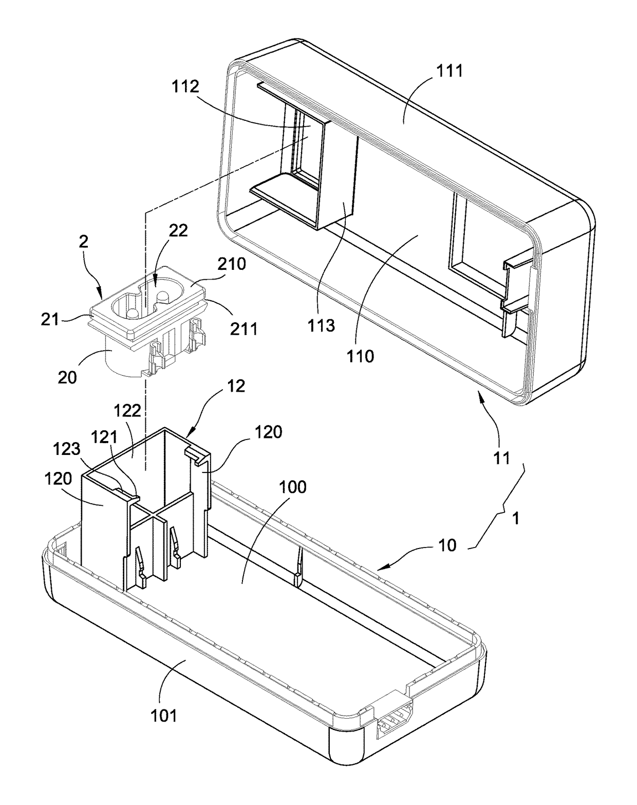
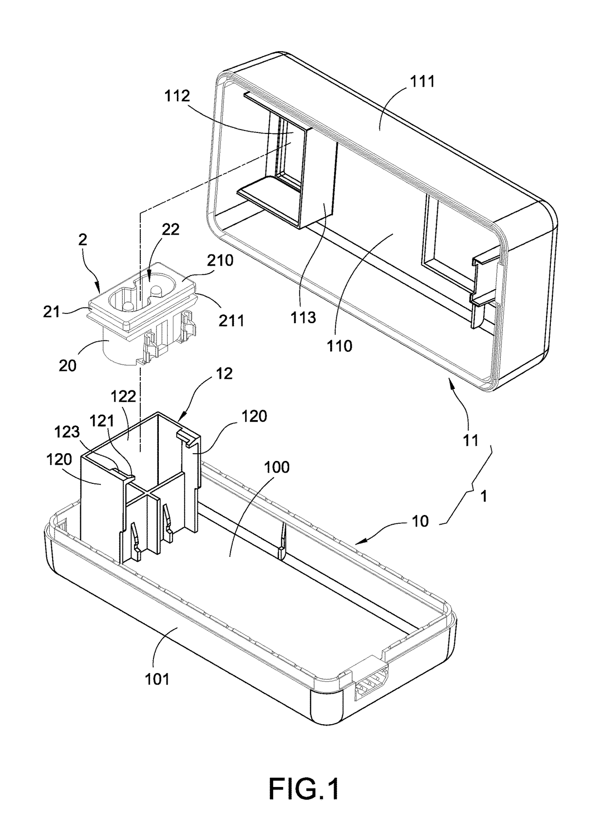
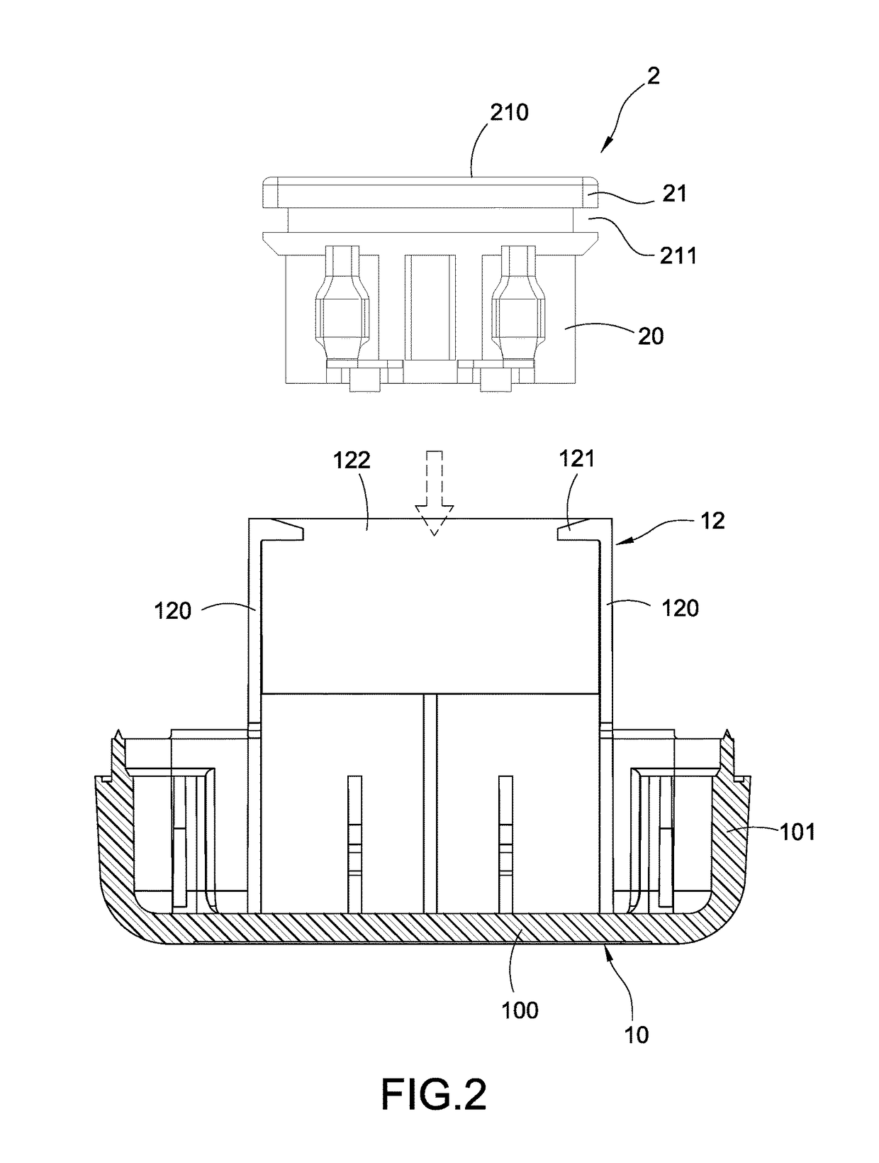
[0016]With reference to FIG. 1 for an exploded view of an adapter casing module and a power socket in accordance with this disclosure, the adapter casing module 1 is provided for installing a power socket 2 and its related electronic components such as a control circuit board (not shown in the figure) into the casing module 1. The power socket 2 has a socket body 20 and a plug end 21 formed on the socket body 20, and the plug end 21 has a jack 22 communicated with the socket body 20, and a related connecting component such as a terminal (not shown in the figure) is installed in the jack 22. The casing module 1 includes a first casing 10 and a seco...


PUM


Abstract

An adapter casing module for installing a power socket includes a first casing and a second casing engaged correspondingly with the first casing, and the first casing has a fixed base, and the second casing has an opening disposed opposite to the fixed base, and the fixed base includes two elastic walls protruded from the first casing, and the two elastic walls are arranged with an interval apart and opposite to each other for installing the power socket between the elastic walls, and a first limit structure is disposed on a side of the two elastic walls, and a second limit structure is disposed on the other side of the two elastic walls, and the first and second limit structures are provided for limiting the power socket to be situated in the fixed base and configured to be corresponsive to the opening of the second casing.

Description

FIELD OF THE INVENTION[0001]This disclosure relates to a power adaptor, and more particularly to an adapter casing module for installing a power socket.BACKGROUND OF THE INVENTION[0002]In general, a power adapter is used as a power conversion accessory of portable electronic products and comprised of a casing, a control circuit board installed in the casing, and components such as inductor, a capacitor, and a transformer installed on the control circuit board and has a power input end and a power output end for inputting an alternating current from the power input end, converting the alternating current (AC) into direct current (DC), and then outputting the DC from the power output end to an electronic product that requires a power supply.[0003]However, the conventional power adapter is formed by a power socket such as an (AC socket) at the power input or output end, and clamped between upper and lower casings, but such assembling method restricts the product, such that the power so...

Claims


Application Information

Patent Timeline
Patent Type & Authority Patents(United States)
IPC IPC(8): H01R13/514H01R31/06H01R13/506H01R13/424
CPCH01R31/06H01R13/506H01R13/424H01R13/518H01R2103/00H01R24/68
Inventor LIN, MING-HUILEE, PO-SHENG
Owner CHICONY POWER TECH CO LTD
Learn More