
Valve seats for use in fracturing pumps

a technology of reciprocating pumps and valve seats, which is applied in the direction of machines/engines, liquid fuel engines, and positive displacement liquid engines, etc., can solve the problems of corrosion, erosion and/or pitting of the surface of the valve assembly, and the replacement of the valve seat is more difficult and cumbersome than the replacement of the valve body

Active Publication Date: 2017-11-21
SPM OIL & GAS INC
View PDF161 Cites 82 Cited by
  • Summary
  • Abstract
  • Description
  • Claims
  • Application Information

AI Technical Summary

Problems solved by technology

This fluid often contains solid particulates or corrosive material that can cause corrosion, erosion and / or pitting on surfaces of the valve assembly.
During operation, solid particulates are oftentimes trapped between the interacting surfaces of the valve body and the valve seat, causing erosion and pitting of these surfaces.
Because the valve seat is securely fastened within the fluid end, it is more difficult and cumbersome to replace the valve seat than the valve body.
For example, a valve seat is oftentimes fixed inside the fluid passageway by way of an interference fit; thus, removing the valve seat from the fluid passageway oftentimes increases the risk of damage to the pump fluid end.

Method used


Image

  • Valve seats for use in fracturing pumps
  • Valve seats for use in fracturing pumps
  • Valve seats for use in fracturing pumps

Examples


Embodiment Construction

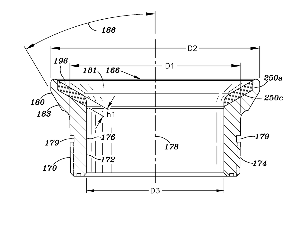
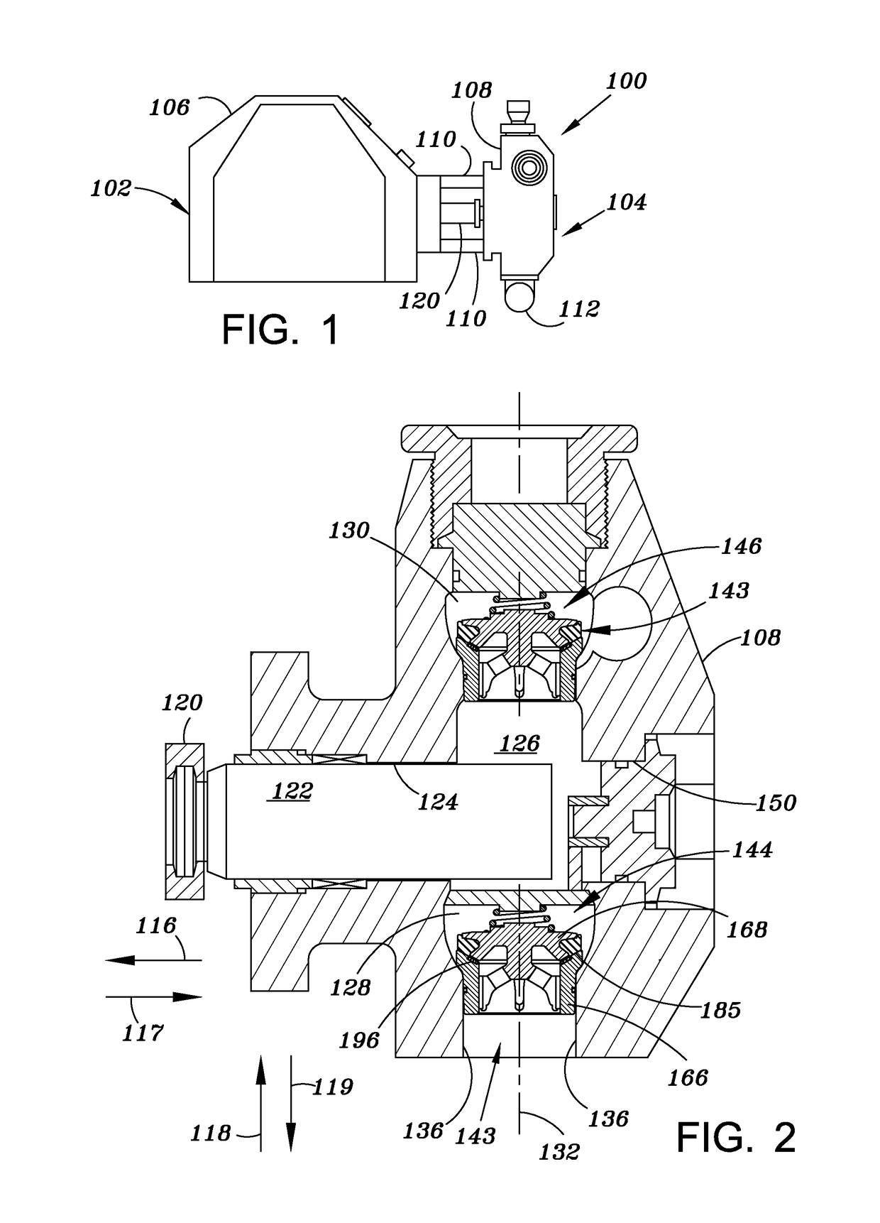
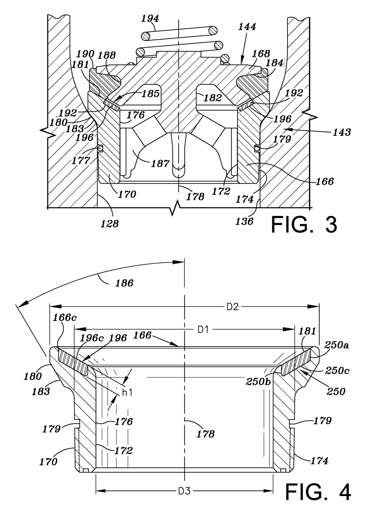
[0060]Referring to FIGS. 1-3, an illustrative embodiment of a reciprocating pump assembly 100 is presented in which an insert 196 (FIG. 3) is employed to reduce damage to, and thus, extend the operating life of, a valve assembly 143, due to corrosion, erosion, pitting or the like. In the embodiment illustrated in FIGS. 1-3, the insert 196 is formed of a high strength ceramic material; however, it should be understood that insert 196 may be otherwise formed. In FIGS. 1-3, the reciprocating pump assembly 100 includes a power end portion 102 and a fluid end portion 104 operably coupled thereto. The power end portion 102 includes a housing 106 in which a crankshaft (not shown) is disposed, the crankshaft is driven by an engine or motor (not shown). The fluid end portion 104 includes a fluid end block or fluid cylinder 108, which is connected to the housing 106 via a plurality of stay rods 110. In operation and as discussed in further detail below, the crankshaft reciprocates a plunger r...


PUM

PropertyMeasurementUnit
angleaaaaaaaaaa
pressuresaaaaaaaaaa
pressuresaaaaaaaaaa

Abstract

A valve seat at least partially formed of a ceramic material for use in a fracturing pump includes a first body and a second body. The first body is configured to be inserted into a fluid passageway of the fracturing pump. The first body has an outer diameter, D1. The second body extends radially from the first body and has an outer diameter, D2, greater than the outer diameter, D1, of the first body. The second body is at least partially formed of the ceramic material.

Description

CROSS-REFERENCE TO RELATED APPLICATION[0001]This Application claims priority to and the benefit of U.S. Provisional Patent Application Ser. No. 61 / 909,197, filed on Nov. 26, 2013, which is incorporated herein by reference in its entirety.TECHNICAL FIELD[0002]This disclosure relates to reciprocating pumps, and, in particular, to valve seats used in reciprocating pumps.BACKGROUND OF THE DISCLOSURE[0003]In oilfield operations, reciprocating pumps are used for different applications such as fracturing the subterranean formation, cementing the wellbore, or treating the wellbore and / or formation. A reciprocating pump typically includes a power end and a fluid end or cylindrical section. The fluid end is typically formed of a one piece construction or a series of blocks secured together by rods. The fluid end includes an opening for receiving a plunger or plunger throw, an inlet passage, an outlet passage, and an access port. Reciprocating pumps are oftentimes operated at pressures of 10,0...

Claims


Application Information

Patent Timeline
Patent Type & Authority Patents(United States)
IPC IPC(8): F16K25/00F16K15/06F04B53/10F04B1/04F16K1/46F16K1/42
CPCF16K25/005F04B1/0452F04B53/10F16K15/063F16K1/42F16K1/465F04B53/1087
Inventor BAYYOUK, JACOB A.PEACH, KEITH
Owner SPM OIL & GAS INC
Learn More