Thermistor fixing structure, thermistor removing method, and air-conditioning apparatus

a technology of removing method and fixing structure, which is applied in the direction of lighting and heating apparatus, instruments, heat measurement, etc., can solve the problems of degrading workability and easy detachment of the thermometer from the temperature sensitive cylinder, and achieve the effect of enhancing workability and easy detachmen

Inactive Publication Date: 2017-11-14
MITSUBISHI ELECTRIC CORP
View PDF29 Cites 3 Cited by
  • Summary
  • Abstract
  • Description
  • Claims
  • Application Information

AI Technical Summary

Benefits of technology

[0011]The present invention has been made to solve the problems as described above, and it is therefore a first object of the present invention to provide a thermistor fixing structure capable of facilitating insertion of a thermistor into a temperature sensitive cylinder, and preventing the thermistor from easily dropping off the temperature sensitive cylinder.
[0012]It is a second object of the present invention to provide a thermistor removing method for easily removing the thermistor fixed to the thermistor fixing structure from the temperature sensitive cylinder.
[0018]Thus, even when the insertion of the thermistor is facilitated by reducing the pressing force for pressing the thermistor with the pressing section, the removal of the thermistor is disabled or restricted, and thus the pressing section, that is, the fixture can be downsized and light-weighted.
[0019](ii) In the thermistor removing method according to the one embodiment of the present invention, the thermistor is removed from the temperature sensitive cylinder under a state in which the separation plate member is thrust into the abutting portion between the distal end of the pressing section and the side surface of the thermistor, and hence the pressing section is slid along the separation plate member. Thus, the distal end of the pressing section does not dig into the side surface of the thermistor, thereby facilitating the removal of the thermistor.
[0020](iii) Further, the air-conditioning apparatus according to the one embodiment of the present invention includes the thermistor fixing structure according to the embodiment (1), which is mounted to the refrigerant pipe. Therefore, for example, even when the lead wire connected to the thermistor is unintentionally pulled at the time of assembling, or when the lead wire is caught on any portion, the thermistor is not easily detached from the temperature sensitive cylinder. Thus, the workability is enhanced at the time of assembling.

Problems solved by technology

In this case, there is a problem in that, for example, when a lead wire connected to the thermistor is unintentionally pulled at the time of assembling, or when the lead wire is caught on any portion, the thermistor is easily detached from the temperature sensitive cylinder.
When the spring force is increased so as to prevent the thermistor from being easily detached from the temperature sensitive cylinder, on the other hand, a greater force is required to insert the thermistor into the temperature sensitive cylinder, thereby leading to a problem in that the workability is degraded.

Method used


Image

  • Thermistor fixing structure, thermistor removing method, and air-conditioning apparatus
  • Thermistor fixing structure, thermistor removing method, and air-conditioning apparatus
  • Thermistor fixing structure, thermistor removing method, and air-conditioning apparatus

Examples


first embodiment

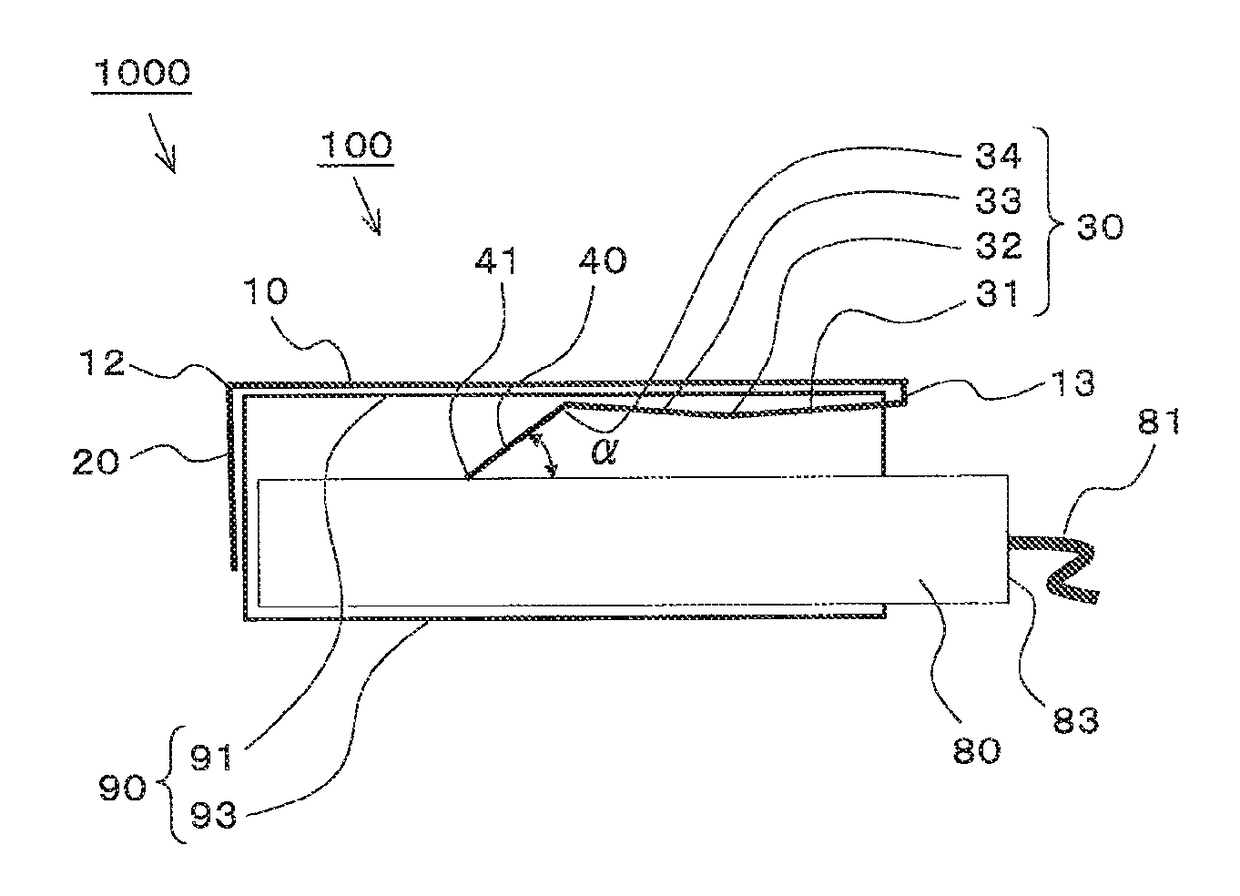
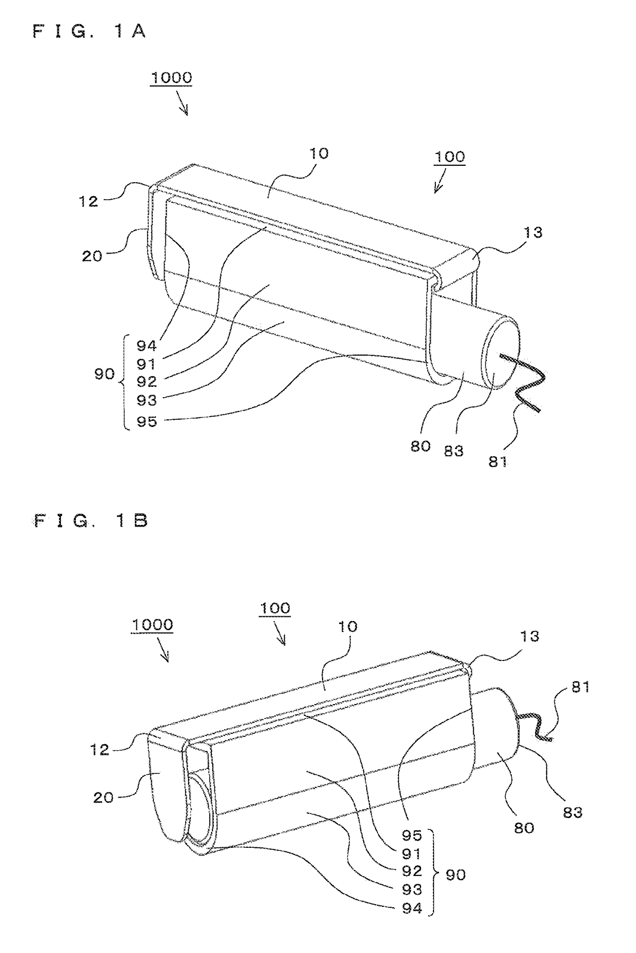
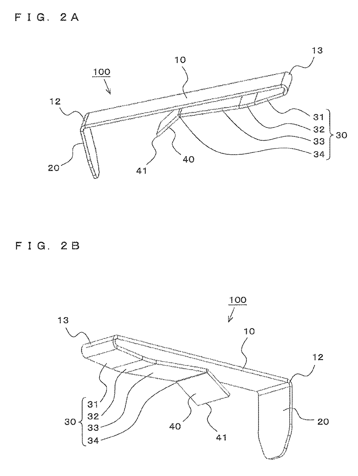
[0034]FIGS. 1A to 4C illustrate a thermistor fixing structure according to a first embodiment of the present invention. FIGS. 1A and 1B are entire perspective views each illustrating the thermistor fixing structure. FIGS. 2A and 2B are perspective views each illustrating a part (fixture) of the thermistor fixing structure. FIG. 3 is an entire side sectional view illustrating the thermistor fixing structure. FIGS. 4A to 4C are side views each illustrating a function of the part (fixture) of the thermistor fixing structure. Note that, the respective figures are schematic views, and the present invention is not limited to the illustrations of the respective figures.

[0035](Thermistor Fixing Structure)

[0036]In FIGS. 1A and 1B, a thermistor fixing structure 1000 includes a temperature sensitive cylinder 90 having openings at both ends thereof, a thermistor 80 inserted into the temperature sensitive cylinder 90, and a fixture 100 including a pressing section 40 (see FIGS. 2A and 2B) for pr...

second embodiment

[0061]FIGS. 5A to 6 illustrate a thermistor fixing structure according to a second embodiment of the present invention. FIGS. 5A and 5B are perspective views each illustrating a part (fixture) of the thermistor fixing structure. FIG. 6 is an entire side sectional view illustrating the thermistor fixing structure. Note that, the same or corresponding parts as or to those of the first embodiment are represented by the same reference symbols, and the description is partially omitted herein. Further, the respective figures are schematic views, and the present invention is not limited to the illustrations of the respective figures.

[0062]In FIGS. 5A, 5B, and 6, a thermistor fixing structure 2000 includes the temperature sensitive cylinder 90, the thermistor 80, and a fixture 200 including the pressing section 40 and the projecting portion 32 for pressing the thermistor 80 against the inner surface of the temperature sensitive cylinder 90.

[0063]The fixture 200 is formed by modifying the fi...

third embodiment

[0067]FIGS. 7A to 8 illustrate a thermistor fixing structure according to a third embodiment of the present invention. FIGS. 7A and 7B are entire perspective views each illustrating the thermistor fixing structure. FIG. 8 is a perspective view illustrating a part (fixture) of the thermistor fixing structure. Note that, the same or corresponding parts as or to those of the second embodiment are represented by reference symbols with the same last two numbers, and the description is partially omitted herein. Further, the respective figures are schematic views, and the present invention is not limited to the illustrations of the respective figures.

[0068]In FIGS. 7A, 7B, and 8, a thermistor fixing structure 3000 includes a temperature sensitive cylinder 390, the thermistor 80, and a fixture 300 including a pressing section 340 and a projecting portion 332 for pressing the thermistor 80 against an inner surface of the temperature sensitive cylinder 390.

[0069]The fixture 300 is formed by b...


PUM

PropertyMeasurementUnit
contact angleaaaaaaaaaa
temperature sensitiveaaaaaaaaaa
temperatureaaaaaaaaaa

Abstract

Provided is a thermistor fixing structure capable of facilitating insertion of a thermistor into a temperature sensitive cylinder, and preventing the thermistor from easily dropping off the temperature sensitive cylinder. In a thermistor fixing structure (4000), a fixture (400) for pressing a thermistor (80) against an inner surface of a temperature sensitive cylinder (90) includes an inner bending section (20) formed at one end portion (12) of a longitudinal section (10) so as to function as a stopper for the thermistor (80) inserted into the temperature sensitive cylinder (90) from a cylinder insertion end (95), an outer bending section (50) formed at the one end portion (12) of the longitudinal section (10) so as to be opposed to a cylinder stop end (94), and an inner folding section (30) and an outer folding section (60) formed at another end portion (13) of the longitudinal section (10) so as to sandwich a cylinder top surface of the temperature sensitive cylinder (90). A side surface of the thermistor (80) is pressed at two points corresponding to an apex of a projecting portion (32) formed on the inner folding section (30) and a distal end (41) of a pressing section (40) formed continuously with the inner folding section (30), and a contact angle (α) formed between the pressing section (40) and the side surface of the thermistor (80) on the cylinder insertion end (95) side is an acute angle.

Description

BACKGROUND OF THE INVENTION[0001]1. Field of the Invention[0002]The present invention relates to a thermistor fixing structure, a thermistor removing method, and an air-conditioning apparatus, and more particularly, to a thermistor fixing structure having a thermistor fixed to a temperature sensitive cylinder thereof, a thermistor removing method for removing the thermistor fixed to the thermistor fixing structure from the temperature sensitive cylinder, and an air-conditioning apparatus including the thermistor fixing structure.[0003]2. Description of the Related Art[0004]Hitherto, as a thermistor fixing structure, for example, the following invention is disclosed (see, Patent Literature 1). In this invention, a temperature sensitive cylinder is brazed to a temperature detection portion of a refrigerant pipe of a refrigeration cycle apparatus, which is a part to be subjected to temperature detection, and a columnar thermistor is inserted into the temperature sensitive cylinder and ...

Claims


Application Information

Patent Timeline
Patent Type & Authority Patents(United States)
IPC IPC(8): G01K1/14G01K7/22
CPCG01K7/22G01K1/14Y10T29/49085G01K1/146F24F11/89F25B49/02F24F2140/20F25B41/40F25B2700/21F25B2700/2115
Inventor ISHIKAWA, MASATOGOTO, TAKUYASUZUKI, AKIMOTOKINAMI, MASAHIDEIKEDA, HISANORIYOKOTA, SHUHEIKOYANAGI, YOUHEIISHIGAMI, KATSUYA
Owner MITSUBISHI ELECTRIC CORP
Why Eureka
Try Eureka