
Bedstead fastening device

a technology of bedstead and fastening rod, which is applied in the direction of fastening means, furniture joining, sheet joining, etc., can solve the problems of not even certain, excessive force being applied, and noisy bed support function

Inactive Publication Date: 2017-11-14
BILIS IOANNIS
View PDF14 Cites 0 Cited by
  • Summary
  • Abstract
  • Description
  • Claims
  • Application Information

AI Technical Summary

Benefits of technology

[0008]It is the object of the present invention to provide a bedstead fastening device adapted to provide secure attachment and support of bed component parts, i.e. of the rails forming the bedstead and of the bedstead and headboard, wherein the proposed bed fastening device is made from plastic raw material and is characterized in that it provides a noise-free secure attachment of the bed components, wherein the four fastening devices at each one of the four corner posts of the bedstead are adapted to receive equivalent loads and each fastening device is adapted to be equivalently loaded in each one of a plurality of load receiving members and wherein a pair of mating parts in each fastening device are being progressively tightened when being brought in an engagement condition and means is provided in each one of the fastening devices for securely locking the fastening in the finally attained engagement condition and accordingly for appropriately unlocking the same when dismantling of a bed structure is required, such means also adapted to provide an audio signal confirming attainment of the nominal predetermined engagement condition and averting possibilities of misaligned, erroneous engagement that will undoubtedly soon lead to a creaky, noisy connection and a deficient performance of the bed fastening.

Problems solved by technology

It has been observed that usage of the bed eventually leads to deterioration of such fastening means that is being established by the bed becoming generally unsteady due to loose, creaky interconnection of such metallic hook members that in turn results to a noisy bed supporting function as a person lies and moves onto the bed structure.
One reason of such inadequate load bearing capacity is the fact that the load of the bedstead, of the mattress and of the persons lying thereupon is being received by load bearing members exhibiting a rather small loaded surface area that results to excessive forces being applied thereupon.
Furthermore it is not even certain in the assembly of such a fastening member if both abovementioned supporting pins are substantially equally loaded so as receive and share an equivalent load of the bed being supported.
If therefore a slight misalignment occurs in the assembly of a bed structure, this may lead to excessive loading of one component of the bed fastening relative to another that may lead to its inefficient performance and rapid wear.
Thus, bed fastenings of the prior art exhibit a drawback of non-equivalent loading of each one of the load sharing components in each one of the fastenings being employed and accordingly of non-equivalent loading of the four fastenings being employed at the four corner posts of the bedstead.
On the other hand, it is also possible that such hook members get in an undesirably tight interlocking connection that dismantling thereof when disassembly of the bed is required becomes difficult.
It is further also noted that such bedstead fastening devices of the prior art lack means of providing a signal to the person carrying out assembly of the bed structure in confirmation of attainment of the nominal predetermined engagement condition, such lack of signaling attainment of the nominal predetermined engagement condition leading to possibilities of misaligned, erroneous engagement that will undoubtedly soon lead to a creaky, noisy connection and a deficient performance of the bed fastening.
Furthermore the prior art does not teach means of automatically and securely locking the fastenings in their engagement condition and therefore appropriately unlocking the same when dismantling of a bed structure is required.

Method used


Image

  • Bedstead fastening device
  • Bedstead fastening device
  • Bedstead fastening device

Examples


Embodiment Construction

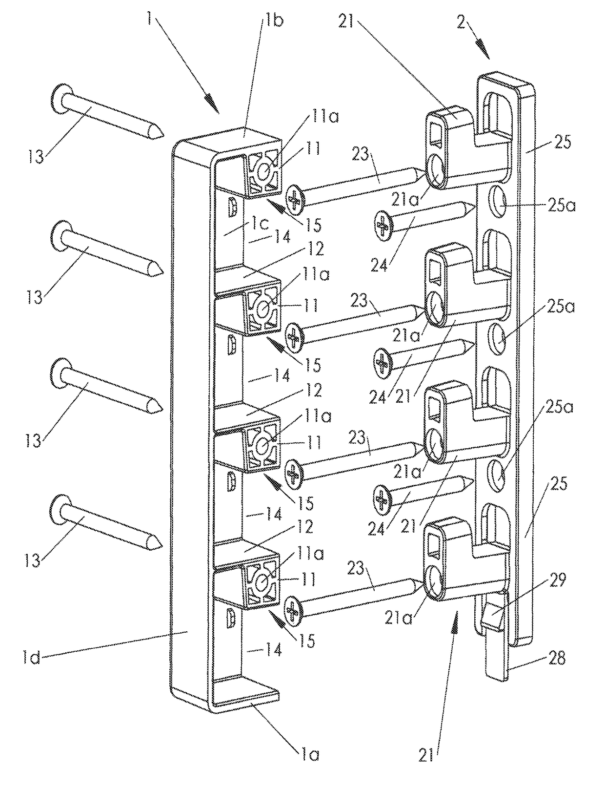
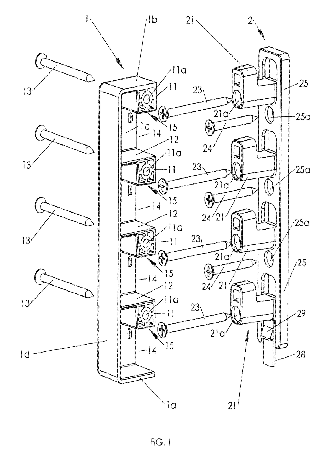
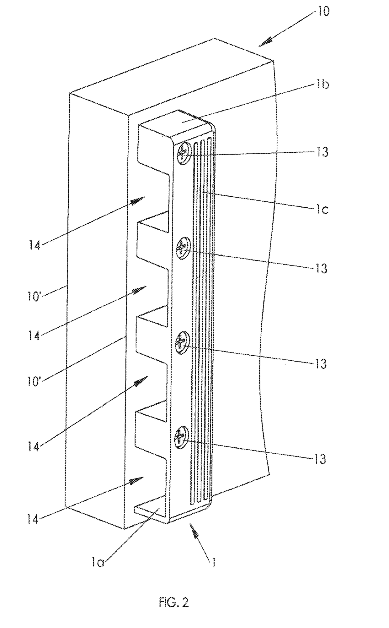
[0020]The invention relates to a bed fastening device used in connecting together the components of a bed structure, such components comprising a pair of side rails extending in the longitudinal direction of the bed structure and a pair of side rails extending in the transverse direction thereof. The four side rails are connected at the four corner posts of the bed structure with an equivalent number of bed fastening devices. In a common bed structure all such side rails have the same configuration and they only differ in their length dimension with the transversal side rails having a length smaller than the longitudinal ones. Often one of the side rails extending in the transverse direction is being configured as a headboard being located at the top of the bed and extending above the level of the mattress. The drawings show the bed fastening device of the invention that comprises a first mating part 1 and a second mating part 2 with the first mating part 1 being mounted proximally ...


PUM


Abstract

A bed fastening device providing connection of the components in a bed structure, including a first mating part and a second mating part correspondingly mounted proximally to one end of bed components. The first mating part includes an elongate parallelepipedal plastic item with equidistantly spaced planar partition walls extending into side housings of tubular members, openings being provided in between sequential partition walls and side housings. The second mating part includes an elongate planar base plastic item with perpendicularly oriented, equidistantly spaced tubular members provided with side extensions. Engagement of the mating parts and of the bed fastening device and accordingly of bed components takes place with the introduction of tubular members of the mating parts within the openings of mating parts and the vertical downward displacement of the mating parts.

Description

RELATED APPLICATION[0001]This application is a national phase entry under 35 USC 371 of International Patent Application No PCT / GR2013 / 000022 filed on 19 Apr. 2013, the disclosures of which are incorporated in their entirety by reference herein.THE FIELD OF THE ART[0002]The present invention is directed to a bedstead fastening device adapted to provide secure attachment and support of bed component parts, i.e. of the rails forming the bedstead and of the bedstead and headboard.THE BACKGROUND OF THE INVENTION[0003]It is commonly known that a variety of fastening means are employed in the interconnection of the rails forming the bedstead, i.e. the frame of a bed structure and in latching the bedstead to the headboard of the bed, such fastening means being applied at the corner posts to interlock one fastening member mounted onto the side rail and extending forwardly thereof with another fastening member mounted onto an adjacent side rail or onto the headboard. A load-bearing capacity ...

Claims


Application Information

Patent Timeline
Patent Type & Authority Patents(United States)
IPC IPC(8): F16B12/56A47C19/02A47C19/00F16B12/22F16B5/07
CPCF16B12/56A47C19/005F16B12/22A47C19/021F16B5/07
Inventor BILIS, IOANNIS
Owner BILIS IOANNIS
Learn More