
Ephemeral electric potential and electric field sensor

a technology of electric potential and electric field, applied in the field of sensors, can solve the problem of not only supporting leakage currents

Active Publication Date: 2017-10-31
NASA
View PDF46 Cites 2 Cited by
  • Summary
  • Abstract
  • Description
  • Claims
  • Application Information

AI Technical Summary

Benefits of technology

This approach enables precise measurement and imaging of electric potentials and fields, overcoming the limitations of existing systems by reducing sensor distortions and allowing for accurate quantification of electric fields, even in the presence of charged objects or environments.

Problems solved by technology

Additionally, the leakage currents are not only supported by solid structures.
This equilibrium process is time dependant and prohibits the measurement of the original true electrical potential and electric field in current systems.

Method used


Image

  • Ephemeral electric potential and electric field sensor
  • Ephemeral electric potential and electric field sensor
  • Ephemeral electric potential and electric field sensor

Examples


Embodiment Construction

[0018]For purposes of description herein, it is to be understood that the specific devices and processes illustrated in the attached drawings, and described in the following specification, are simply exemplary embodiments of the inventive concepts defined in the appended claims. Hence, specific dimensions and other physical characteristics relating to the embodiments disclosed herein are not to be considered as limiting, unless the claims expressly state otherwise.

[0019]The word “exemplary” is used herein to mean “serving as an example, instance, or illustration,” Any implementation described herein as “exemplary” is not to be construed as preferred or advantageous over other implementations.

[0020]The various embodiments will be described in detail with reference to the accompanying drawings. Wherever possible, the same reference numbers will be used throughout the drawings to refer to the same or like parts. References made to particular examples and implementations are for illustr...


PUM


Abstract

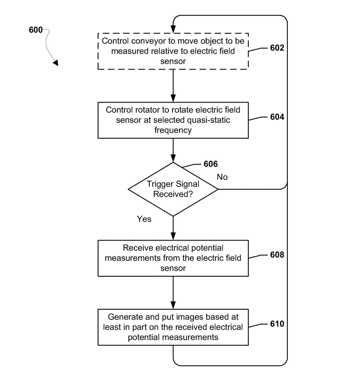
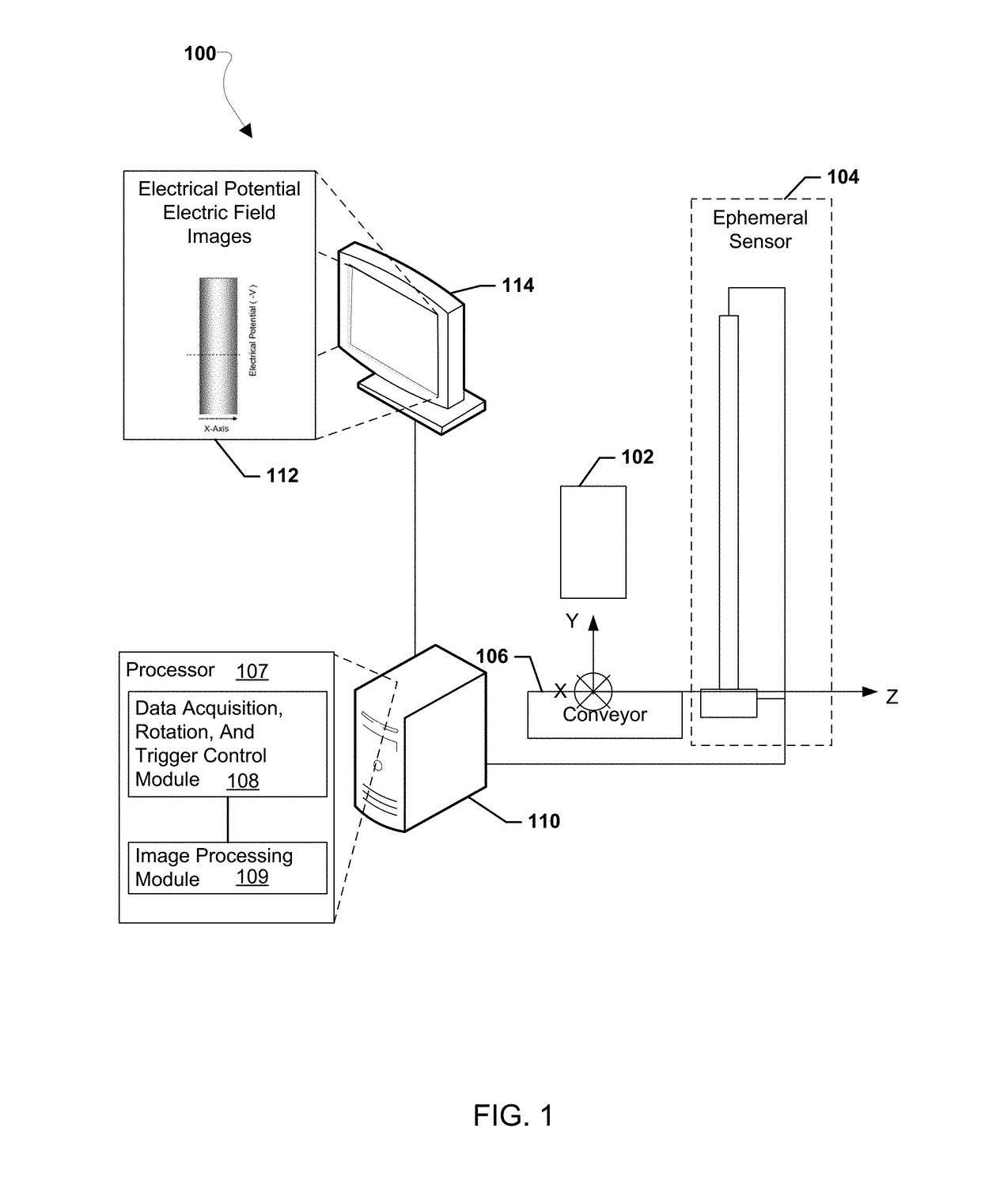
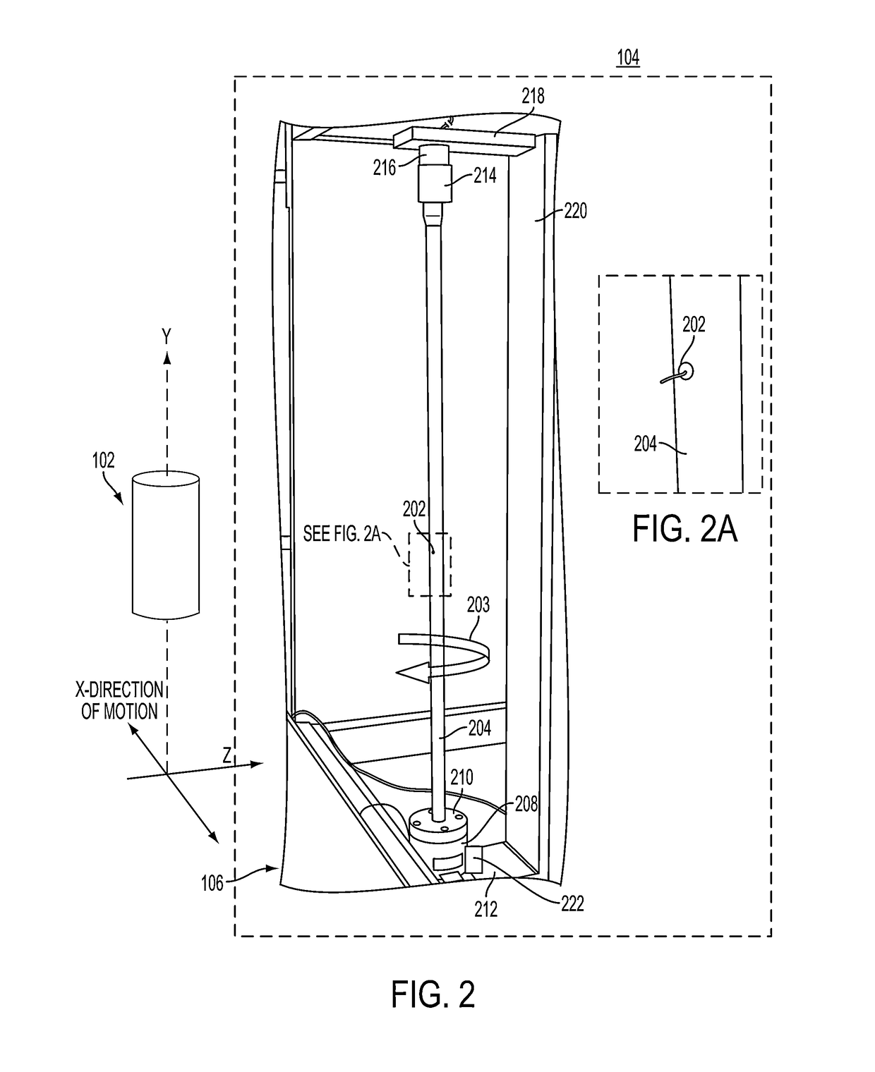
Systems, methods, and devices of the various embodiments provide for the minimization of the effects of intrinsic and extrinsic leakage electrical currents enabling true measurements of electric potentials and electric fields. In an embodiment, an ephemeral electric potential and electric field sensor system may have at least one electric field sensor and a rotator coupled to the electric field sensor and be configured to rotate the electric field sensor at a quasi-static frequency. In an embodiment, ephemeral electric potential and electric field measurements may be taken by rotating at least one electric field sensor at a quasi-static frequency, receiving electrical potential measurements from the electric field sensor when the electric field sensor is rotating at the quasi-static frequency, and generating and outputting images based at least in part on the received electrical potential measurements.

Description

CROSS REFERENCE TO RELATED APPLICATIONS[0001]This application claims the benefit of priority to U.S. Provisional Application No. 61 / 906,068 filed on Nov. 19, 2013 entitled “Ephemeral Electric Potential and Electric Field Sensor”, the entire contents of which are hereby incorporated by reference in their entirety.STATEMENT REGARDING FEDERALLY SPONSORED RESEARCH OR DEVELOPMENT[0002]The invention described herein was made by an employee of the United States Government and may be manufactured and used by or for the Government of the United States of America for governmental purposes without the payment of any royalties thereon or therefore.BACKGROUND OF THE INVENTION[0003]The present invention relates to sensors, and more particularly to sensors for measurements of electric potentials and electric fields.[0004]With an electric field sensor it may be possible to measure the true quantitative electric potential and electrostatic field emanating from, passing through, and present around ob...

Claims


Application Information

Patent Timeline
Patent Type & Authority Patents(United States)
IPC IPC(8): G01R13/02G01R29/12
CPCG01R29/12G01R13/0218
Inventor GENERAZIO, EDWARD R.
Owner NASA
Learn More