
Determining electric grid topology via a zero crossing technique

a technology of electric grid topology and zero crossing, applied in the direction of electric devices, data switching networks, instruments, etc., can solve the problems of overloaded power lines and therefore subject to failure, inaccurate/inaccurate grid topology determined via this type of approach, and high cost and human error normally associated with conventional approaches to determining network topology , to achieve the effect of reducing costs and avoiding human error

Active Publication Date: 2017-10-17
ITRON NETWORKED SOLUTIONS INC
View PDF7 Cites 2 Cited by
  • Summary
  • Abstract
  • Description
  • Claims
  • Application Information

AI Technical Summary

Benefits of technology

The patent text describes a technique that allows utility providers to determine the topology of a three-phase power distribution network without having to visually inspect the entire network. This reduces or avoids the costs and human error associated with conventional approaches.

Problems solved by technology

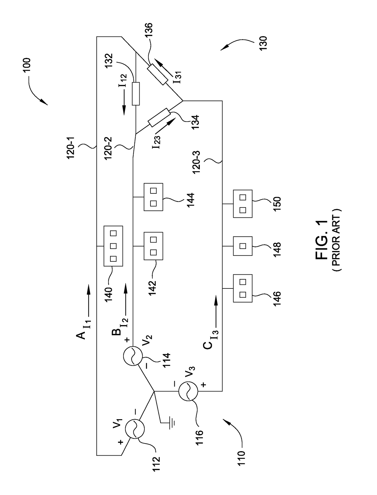
Second, balanced loading may prevent a situation where one power line 120 is underloaded and another power line 120 is overloaded and therefore subject to failure.
The approach outlined above is problematic because visually inspecting power lines to determine grid topology is very time-consuming and costly.
Moreover, the grid topology determined via this type of approach is oftentimes incorrect / inaccurate due to human error.
Consequently, among other things, utility providers typically cannot effectively balance loads across the different power lines within the power distribution network 100, with a reasonable degree of accuracy, which limits the efficiency of three-phase power consumer 130 and increases the susceptibility of power lines 120 to failure.

Method used


Image

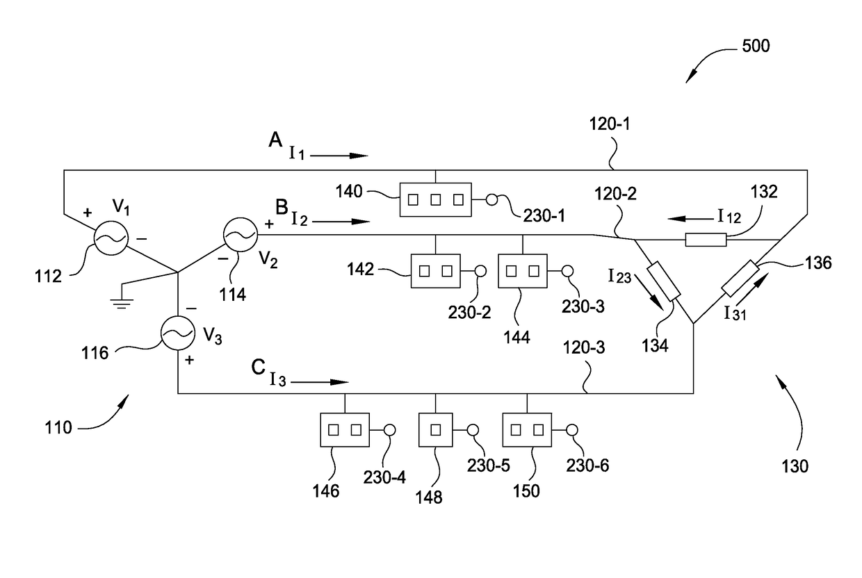
  • Determining electric grid topology via a zero crossing technique
  • Determining electric grid topology via a zero crossing technique
  • Determining electric grid topology via a zero crossing technique

Examples


Embodiment Construction

[0026]In the following description, numerous specific details are set forth to provide a more thorough understanding of the present invention. However, it will be apparent to one of skill in the art that the present invention may be practiced without one or more of these specific details. In other instances, well-known features have not been described in order to avoid obscuring the present invention.

System Overview

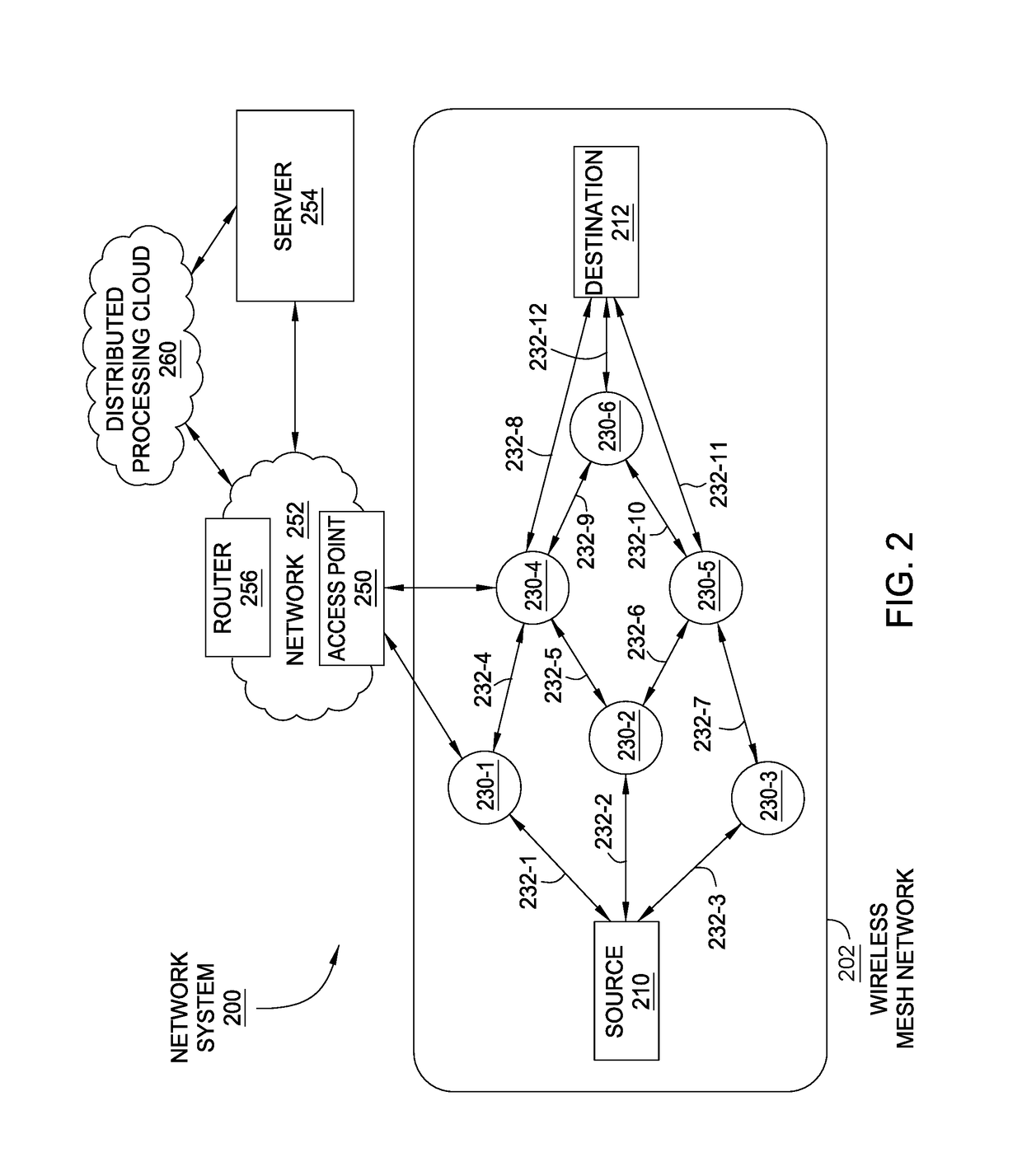
[0027]FIG. 2 illustrates a mesh network configured to operate in conjunction with power distribution network 100 of FIG. 1, according to one embodiment of the present invention. As shown, a network system 200 includes, without limitation, a wireless mesh network 202, which may include a source node 210, intermediate nodes 230 and destination node 212. Source node 210 is able to communicate with certain intermediate nodes 230 via communication links 232. Intermediate nodes 230 communicate amongst themselves via communication links 232. Intermediate nodes 230 communicate wi...


PUM


Abstract

A node within a wireless mesh network is configured to record a zero crossing of alternating current or alternating voltage drawn by a single-phase power consumer and a precise timestamp when the zero crossing occurred, thereby generating timestamped zero crossing data. The node receives similar zero crossing data from a neighboring node. The node then compares the timestamped zero crossing data with the received zero crossing data to determine whether the phase associated with the node is equivalent to, leads, or lags the phase associated with the neighboring node. The node then acquires a positive phase identification associated with the neighboring node. Based on the phase identification, and based on the phase difference between the two nodes, the node infers the phase associated with the single-phase power consumer. That phase indicates the specific power line within a three-phase power distribution network to which the single-phase power consumer is coupled.

Description

CROSS-REFERENCE TO RELATED APPLICATIONS[0001]This application claims the benefit of the following U.S. provisional patent applications titled, “Smart Grid Processing to Evaluate Grid Conditions,” filed Mar. 10, 2014 and having Ser. No. 61 / 950,425, titled, “Distributed Smart Grid Processing,” filed Sep. 3, 2014 and having Ser. No. 62 / 045,423 and entitled, “Distributed Smart Grid Processing,” filed Dec. 19, 2014, and having Ser. No. 62 / 094,907. The subject matter of these related applications is hereby incorporated herein by reference.BACKGROUND OF THE INVENTION[0002]Field of the Invention[0003]Embodiments of the present invention relate generally to electricity grid architecture, and, more specifically, to determining electric grid topology via a zero crossing technique.[0004]Description of the Related Art[0005]FIG. 1 illustrates a conventional three-phase power distribution network 100, according to the prior art. As shown, power distribution network 100 typically includes a power g...

Claims


Application Information

Patent Timeline
Patent Type & Authority Patents(United States)
IPC IPC(8): G08C19/00H02J3/00G01R21/00H02J3/24H04L29/08G01R25/00G06F15/16H04L12/24H04L29/06H04L12/26H02J3/06
CPCG01R25/00G01R21/00H02J3/00H02J3/24H04L41/0803H04L41/0896H04L41/12H04L43/0876H04L43/0888H04L67/125H04L67/16H04L69/28H02J3/06H02J2003/007H04L43/04Y02E60/76Y04S40/22Y04S40/126Y04S40/18H02J2203/20H02J13/00017H02J13/00024H02J13/00034Y02E60/00Y04S40/00Y04S40/20Y04S40/124H02J13/00022H04L67/51H02J3/007
Inventor FLAMMER, III, GEORGE H.SUM, CHARLES P.
Owner ITRON NETWORKED SOLUTIONS INC
Learn More