Deflector device

a deflector and a technology for a vehicle, applied in the direction of roofs, vehicle components, transportation and packaging, etc., can solve the problems of insufficient support rigidity, insufficient longitudinal direction of the vehicle, and achieve the effect of increasing the support rigidity

Active Publication Date: 2017-10-10
MAZDA MOTOR CORP
View PDF8 Cites 0 Cited by
  • Summary
  • Abstract
  • Description
  • Claims
  • Application Information

AI Technical Summary

Benefits of technology

[0004]The present invention has been devised in view of the above-described matter, and an object of the present invention is to provide a deflector device which can properly increase the support rigidity, in the vehicle longitudinal direction, of the deflector.
[0006]According to the present invention, the support rigidity, in the vehicle longitudinal direction, of the deflector plate can be properly increased and also a vertical length (height) of the deflector device can be properly made small. Specifically, since the deflector plate is disposed between the front support member and the rear support member, contacting these support members, the deflector plate is supported so stably by the both support members that the support rigidity, in the vehicle longitudinal direction, of the deflector plate properly increases. Further, since the deflator lower portion of the deflector plate is formed at the position where the deflector lower portion located at the lowermost position does not interfere with the joint portions for joining the both support members and also the elevating mechanism to elevate or lower the deflector plate is provided between the deflector lower portion and the front or rear support members, the vertical length (height) of the deflector device becomes properly small.
[0008]According to this embodiment, a spring base portion (i.e., an end portion of the spring which is connected to the front or rear support members) can be located at an area where the above-described downward-projecting deflector lower portion does not exist (i.e., the portion located in the vicinity of the joint portion), thereby a thickness, in the vehicle longitudinal direction, of the deflector device can be properly shortened.
[0009]Herein, it is preferable that the above-described elevating mechanism further comprise a vertically-extending groove portion provided at the front or rear support members and a pin provided at the deflector lower portion, the pin being configured to engage with the groove portion. Thereby, the thickness, in the vehicle longitudinal direction, of the deflector device can be further properly shortened.
[0010]Furthermore, it is preferable that one of both end portions of the spring which is positioned on the side of the deflector plate be configured to engage with the pin and a recess face portion which is configured to avoid interference with the spring when the deflector plate is located at the lowermost position be provided at the deflector lower portion. The above-descried shortening the longitudinal thickness of the deflector device can be further achieved.

Problems solved by technology

However, in a case in which the deflector is supported by a link member and a biasing spring like the device disclosed in the above-described patent document, there is a concern that the support rigidity, in a vehicle longitudinal direction, of the deflector may be not sufficient.

Method used


Image

  • Deflector device
  • Deflector device
  • Deflector device

Examples


embodiment 1

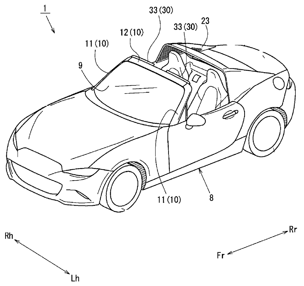
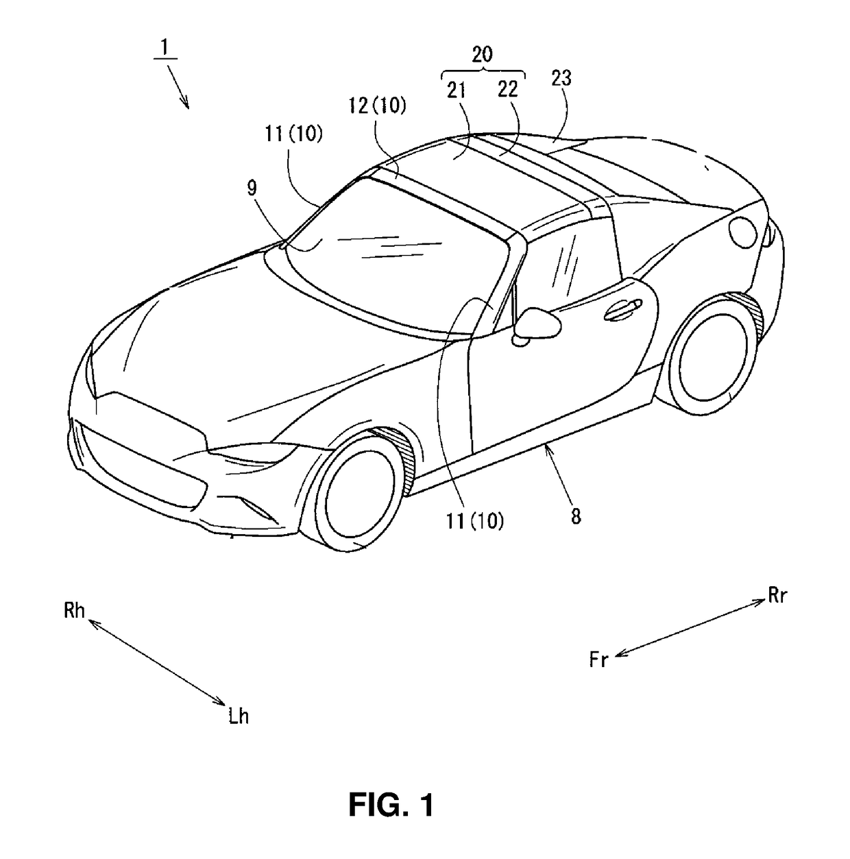
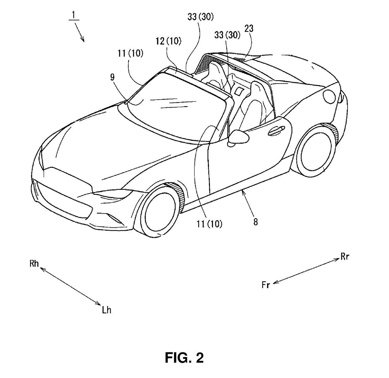
[0027]In the drawings, arrows Fr and Rr show a vehicle longitudinal direction: the arrow Fr showing a vehicle forward direction and the arrow Rr showing a vehicle rearward direction. Further, arrows Rh and Lh show a vehicle width direction: the arrow Rh showing the vehicle rightward direction and the arrow Lh showing a vehicle leftward direction. Additionally, an upper portion of the drawings shows a vehicle upper side and a lower side of the drawings shows a vehicle lower side.

[0028]An openable roof 20 of a vehicle 1 comprises a roof front portion 21 which is detachably connected to an upper portion of a window frame member 10 and a roof rear portion 22 which is positioned in back of the roof front portion 21. The openable roof 20 is storable in a storage space (not illustrated) formed below a deck cover 23 which is of a roughly gate shape in a front view and positioned in back of a vehicle compartment portion 8. In the figures, reference character 24 denotes a rear window glass.

[0...

embodiment 2

[0068]Next, a deflector device 40 to elevate or lower the deflector plate 33 according to a second embodiment, which is different from the above-described deflector device 30 of the first embodiment, will be described referring to FIGS. 12A and 12B. The same structures as the first embodiment are denoted by the same reference characters, detailed descriptions of which are omitted here. In FIGS. 12A and 12B, illustration of the rear support member 34 is omitted.

[0069]The deflector device 40 of the second embodiment is different from the deflector device 30 of the first embodiment in respective shapes of an inward torsion spring 41, the front support member 32, and the deflector plate 33. The inward torsion spring 41 is laterally symmetrical relative to the outward torsion spring 36 as shown in FIGS. 12A and 12B.

[0070]At a rear face of the front support member 32 are provided a first end insertion hole (not illustrated) which opens at a position located near an inward side, in the veh...


PUM


Abstract

Front and rear support members which support a deflector plate configured to project upward above a front header when a roof is open include respective joint portions where respective lower portions thereof are joined to each other. The deflector plate includes deflector lower portions which project downward at respective positions where the deflector lower portions do not interfere with the joint portions of the front and rear support members when the deflector plate is located at a lowermost position. An elevating mechanism (springs, groove portions pins) which is configured to elevate or lower the deflector plate relative to the front and rear support members is provided between the deflector lower portions and the front or rear support members.

Description

BACKGROUND OF THE INVENTION[0001]The present invention relates to a deflector device which is provided at a front header positioned at an upper side of a windshield of a vehicle equipped with an openable roof.[0002]In a so-called open car, there occur a noise caused by traveling air entrapped into a vehicle compartment (a so-called air-entrapping noise air), a noise caused by the traveling air hitting against a window frame supporting a windshield (a so-called wind noise), and the like when an openable roof is open. Accordingly, a deflector device to suppress such peculiar noises occurring when the openable roof is open has been proposed.[0003]A device disclosed in Japanese Patent Laid-Open Publication No. 59-124432 discloses can elevate or lower an air deflector with a simple mechanism, thereby suppressing the peculiar noises occurring when the openable roof is open. However, in a case in which the deflector is supported by a link member and a biasing spring like the device disclos...

Claims


Application Information

Patent Timeline
Patent Type & Authority Patents(United States)
IPC IPC(8): B60J7/22
CPCB60J7/223
Inventor MORIYAMA, YUKIHIRO
Owner MAZDA MOTOR CORP
Why Eureka
Try Eureka