Capacitively readable encoded multilayer body

a multi-layer body, capacitive technology, applied in the field of multi-layer bodies, can solve the problems of encoding that is not supposed to be directly visible, danger of being easily copied, limitations in a design in this regard, etc., to achieve a high level of protection against forgery, increase the visibility of the relief structure as a reflective layer, and increase the effect of the protection level

Active Publication Date: 2017-10-03
POLYIC GMBH & CO KG +2
View PDF18 Cites 0 Cited by
  • Summary
  • Abstract
  • Description
  • Claims
  • Application Information

AI Technical Summary

Benefits of technology

[0037]The microstructure can have largely the same structure parameters, such as e.g. structure depth, azimuth angle, relief shape, over its whole area of surface, or these structure parameters or the type of the microstructure can vary over the area of surface of the microstructure and thereby form a motif. The motif can be formed as an individual image or as an endless motif pattern. The motif or the microstructure can be formed registered, i.e. positionally accurate, relative to the areas or partial areas of the electrically conductive material or can form a pattern independently thereof, i.e. not positionally accurate. The positional accuracy between the areas or partial areas of the electrically conductive material and the microstructure usually varies between + / −1 mm in the x- and y-direction and + / −0 mm. The fact that an encoding that cannot be recognized by the human eye without aids is provided by the arrangement of the electrically conductive material is concealed by the optically variable effect. The surface coverage with the electrically conductive material determines the visibility and / or recognizability of the optical security features if the electrically conductive material serves as a reflective layer for optical security features. If the surface coverage is low, the electrically conductive material is also only present in a low surface coverage as a reflective layer for the optical security feature and the corresponding security feature is of comparatively low brilliance or can be recognized in a high- or low-contrast manner. As the surface coverage of the electrically conductive material serving as reflective layer increases, so do the brilliance, the contrast and the recognizability of these optical security features. To increase the visibility of the optical security features, in addition to the electrically conductive layer an additional non-conductive reflective layer, in particular over the whole surface, can be provided, in particular made of non-conductive materials with a high refractive index, so-called HRI materials (HRI=High Refractive Index).
[0061]In a preferred embodiment, the electrically conductive material is metal, which is first applied over the whole surface and then removed in areas. A demetallization process such as, for example, mechanical removal, etching processes by means of etch resists, washing mask processes by means of washing resists, laser ablation or light-exposure processes by means of photoresists has proved to be particularly efficient. Metal can also be applied particularly well, e.g. by vapor deposition, and has the advantage that it strongly reflects light. For example, the metal can be applied to a relief structure, in particular molded in a varnish layer, whereby the thin metal layer follows the contour of the relief structure and thereby advantageously increases the visibility of the relief structure as a reflective layer. After the application over the whole surface, the metal layer can be demetallized in areas of surface as described above, i.e. removed in areas of surface.

Problems solved by technology

Whenever the encoding of an item of information by electrically conductive areas is to serve as a security function, there is the problem that the encoding is not supposed to be directly visible; it is supposed to be able to be read exclusively with the aid of the relevant reader, but not to be recognizable on the basis of a simple observation.
As soon as the encoding is visually recognizable, there would, namely, be the danger that it could be easily copied.
Because of the opaque cover layer there are limitations in a design in this regard.

Method used


Image

  • Capacitively readable encoded multilayer body
  • Capacitively readable encoded multilayer body
  • Capacitively readable encoded multilayer body

Examples


first embodiment

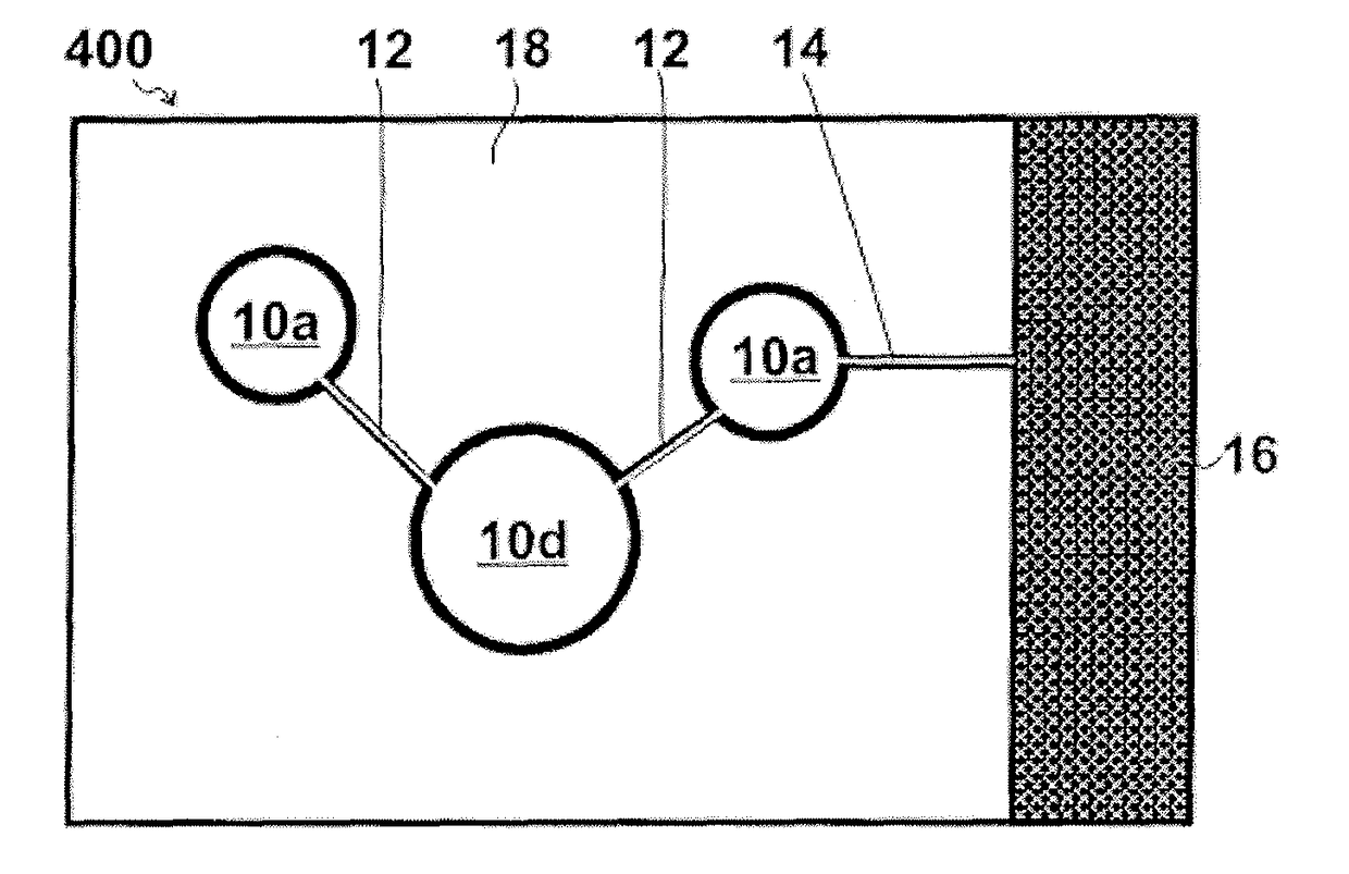
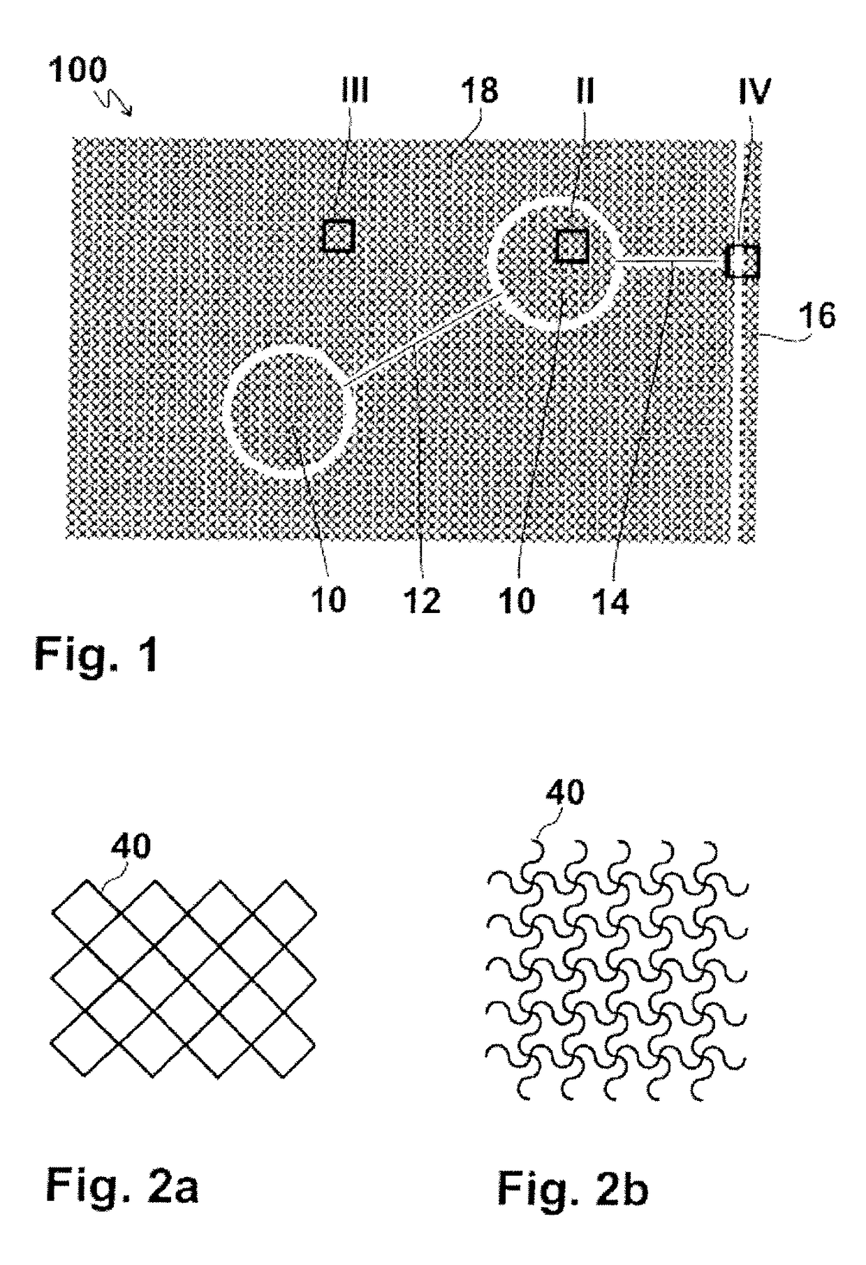
[0084]A multilayer body labeled 100 as a whole according to the invention illustrated in FIGS. 1 to 4b comprises an information area which comprises two first zones 10 which are circular in the present case and which are connected to each other by a connecting line 12. A connecting line 14 leads to an edge area 16, where an electrical connection of the first zones 10 can take place. For example an operator can hold the multilayer body in the edge area 16 and ground it in this way.

[0085]In the information area electrically conductive material is provided which is conductively connected over the whole information area. If the multilayer body 100 is positioned on a touch panel which capacitively detects the approach of an input object (such as for instance a user's finger), then if the size is comparable the first zones 10 act like fingertips of a user's finger. It is advantageous here if the multilayer body 100 is touched in the edge area 16 by an operator and in this way is connected...

second embodiment

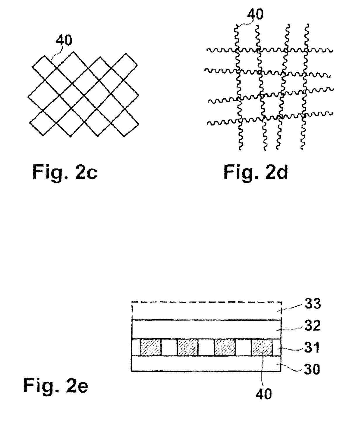
[0105]In the multilayer body the effect is to be achieved that it has a metallic gloss. Here, therefore, metal is provided directly particularly over a large surface area, and in the layer structure according to FIG. 2e, instead of the conductive traces 40, a continuous metal layer made of one of the above-named metals is provided which is only interrupted in areas.

[0106]FIG. 5 shows a top view of such a second embodiment of the multilayer body 200 with an identical geometry to that in the multilayer body 100. Here, for reasons of representability, metallized areas are represented with a white surface, and non-metallized areas are represented in black. This inverted representation is also chosen in FIGS. 6a, 6b, 7, 8, 9, 10 and 11a (but not 11b) as well as 12.

[0107]FIG. 6a shows the formation in an area of a first zone identified by VI in FIG. 5: here metal is provided continuously in the section, which is square in the present case, there are thus no breaks in the first zone. In th...


PUM


Abstract

A multilayer body with a carrier and a layer arranged thereon which comprises electrically conductive material in such an arrangement comprises an information area and a background area (18) which are galvanically separated from each other. In each information area a first zone (10) with electrically conductive material is provided, over the entirety of which electrically conductive material is conductively connected to it. In each background area a plurality of second zones with electrically conductive material is provided, which are galvanically separated from each other. Each first zone (10) preferably occupies a surface area that is at least five times larger than each of the second zones. The electrically conductive material is preferably provided with an average surface coverage which varies over all information areas and background areas (18) by less than 25%. A homogeneous appearance of the multilayer body is thereby ensured, and an item of information provided in the information area, provided by the shape, size and / or alignment of the first zone, is not visible without aids, and therefore cannot be copied.

Description

[0001]This application claims priority based on an International Application filed under the Patent Cooperation Treaty, PCT / EP2014 / 053689, filed on Feb. 26, 2014, and German Application No. DE 102013101881.5, filed on Feb. 26, 2013.BACKGROUND OF THE INVENTION[0002]The invention relates to a multilayer body as well as a method for producing a multilayer body.[0003]This is in particular a multilayer body in which, by an arrangement of electrically conductive material in a layer on a carrier, an item of information is encoded which is capacitively readable.[0004]The multilayer body can be formed in particular in the form of a transfer film, a laminating film or a security thread. The multilayer body can be applied to or integrated into a plurality of different substrates, in particular banknotes, credit cards, identification documents, passports, tickets, travel and admission tickets, travel documents, product packaging, tags, playing cards etc.[0005]Thus it is known from WO 2011 / 15452...

Claims


Application Information

Patent Timeline
Patent Type & Authority Patents(United States)
IPC IPC(8): G06K19/077B42D25/355G06K19/067B42D15/08
CPCG06K19/07754B42D15/085B42D25/355G06K19/067G06K19/07722B42D2033/46
Inventor FIX, WALTERWALTER, MANFREDTOMPKIN, WAYNE ROBERTSCHILLING, ANDREASSCHMIDT, KLAUSMETZGER, JURGEN
Owner POLYIC GMBH & CO KG
Why Eureka
Try Eureka