Control method of an inkjet printer, and inkjet printer

a technology of inkjet printer and control method, which is applied in the direction of printing, instruments, visual presentation, etc., can solve the problems of increasing the length of time, increasing the cost of suction fan operation, etc., to suppress the unnecessary operation of the suction fan and increase the length of time

Active Publication Date: 2017-10-03
SEIKO EPSON CORP
View PDF7 Cites 9 Cited by
  • Summary
  • Abstract
  • Description
  • Claims
  • Application Information

AI Technical Summary

Benefits of technology

[0007]An inkjet printer having a suction fan disposed to a platen according to the invention suppresses increasing the length of time required to complete printing while suppressing unnecessary operation of the suction fan.
[0009]An inkjet printer having a suction unit disposed to a platen according to this configuration of the invention can suppress unnecessary operation of the suction fan while suppressing increasing the time required until printing ends.
[0011]This configuration uses the data structure of the control data to start operation of the suction fan as soon as it is confirmed that printing will start, and can effectively prevent increasing the time required to complete printing.
[0013]This configuration can prevent the suction fan from operating unnecessarily.
[0023]An inkjet printer having a suction unit disposed to a platen in this aspect of the invention can suppress unnecessary operation of the suction fan while suppressing increasing the time required for printing to end.

Problems solved by technology

When the suction unit operates in an inkjet printer having a suction unit as described above, driving the suction unit produces noise, power is consumed by operating the suction unit, and wear (aging) progresses as the suction unit is driven.
Configurations that drive the suction fan once physical operations related to printing start take time for rotation of the suction fan to stabilize after the suction fan starts operating, and therefore increase the amount of time required to finish printing.

Method used


Image

  • Control method of an inkjet printer, and inkjet printer
  • Control method of an inkjet printer, and inkjet printer
  • Control method of an inkjet printer, and inkjet printer

Examples


Embodiment Construction

[0037]A preferred embodiment of the present invention is described below with reference to the accompanying figures.

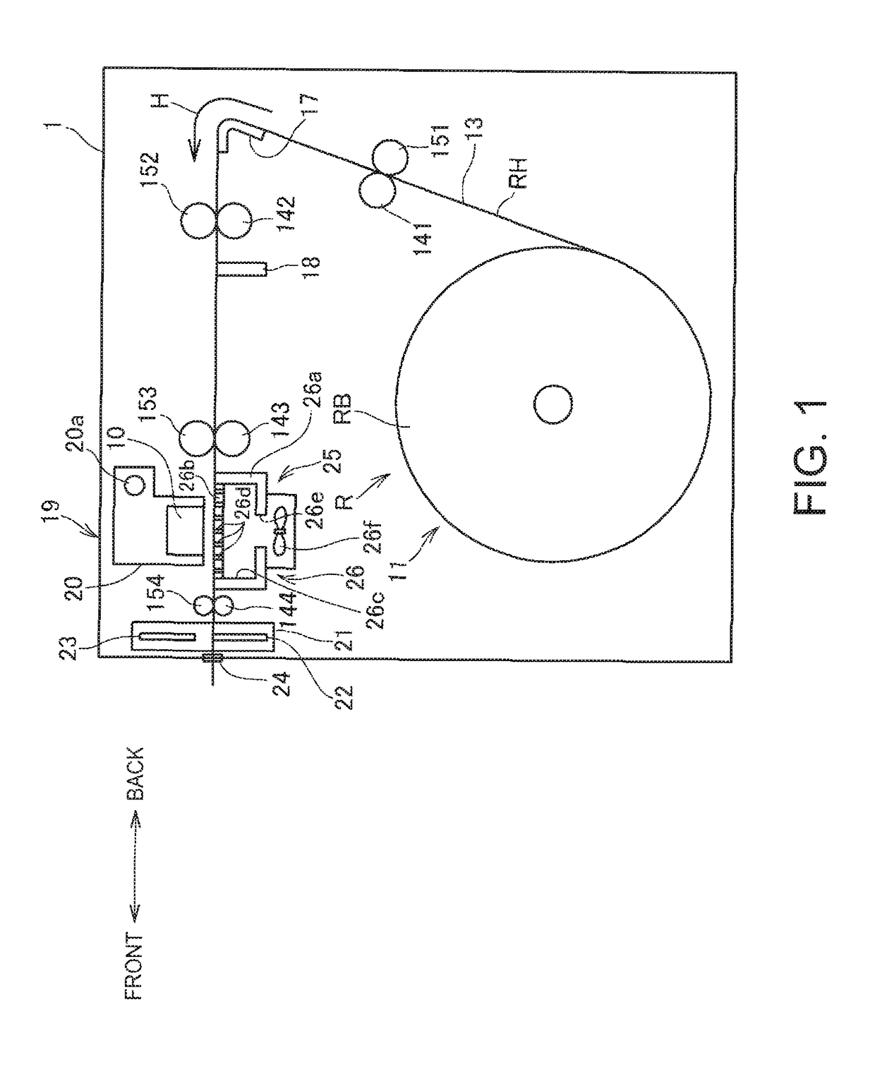
[0038]FIG. 1 illustrates the configuration of main components of an inkjet printer 1 according to this embodiment of the invention.

[0039]In the following description referring to FIG. 1, the direction between the front and back of the printer is indicated by the arrow in FIG. 1.

[0040]The inkjet printer 1 that stores roll paper R (recording media) inside, conveys the stored roll paper R in the conveyance direction H, and prints images by ejecting ink onto the roll paper R by an inkjet head 10, which in this example is a serial head.

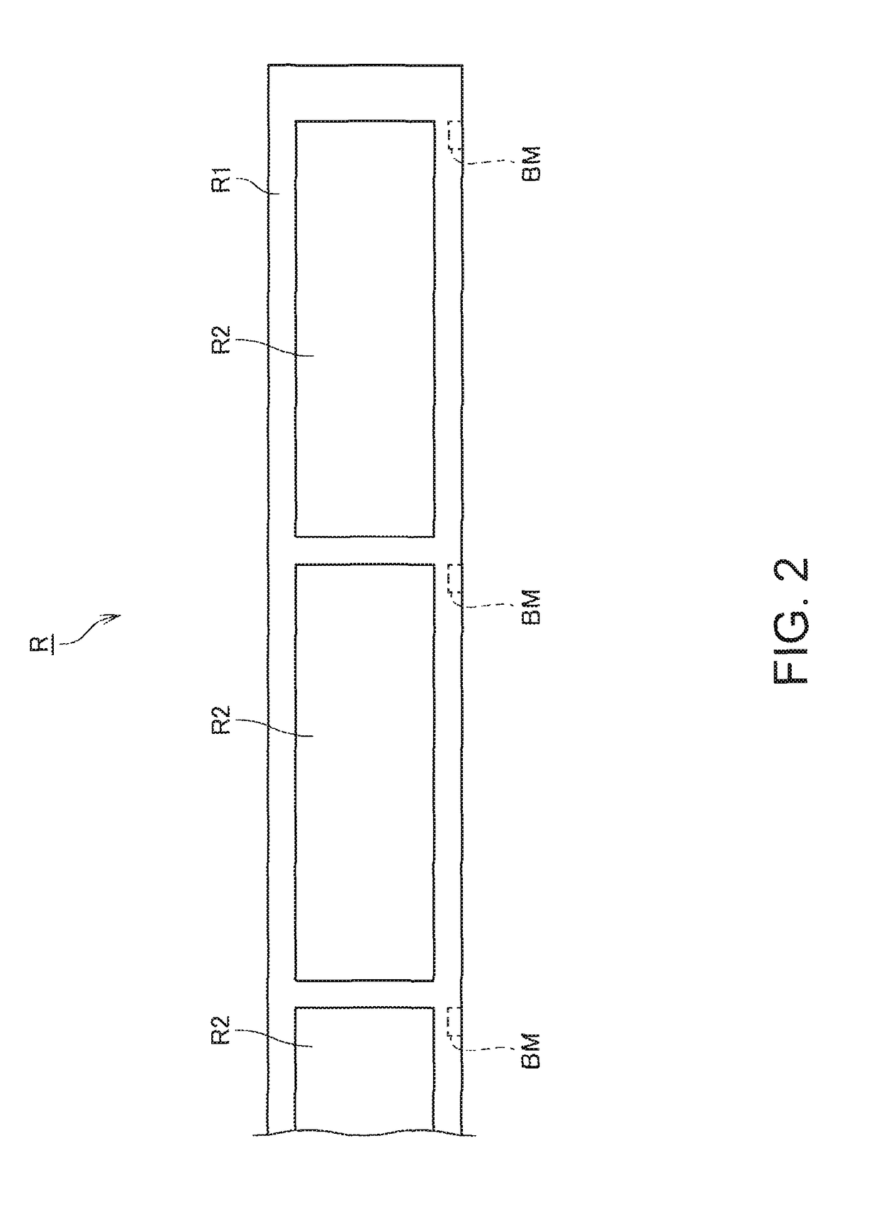
[0041]FIG. 2 shows an example of roll paper R used in the inkjet printer 1.

[0042]The roll paper R shown in FIG. 2 is label paper (paper) having multiple labels R2 affixed with gaps therebetween to a continuous liner R1 (sheet). The back side of the labels R2 is adhesive, and the labels R2 can be peeled from the liner R1 along the label edges....


PUM


Abstract

An inkjet printer having a platen to which a suction unit is disposed suppresses increasing the time required for printing to end and suppresses unnecessary operation of the suction fan. The inkjet printer 1 receives control data from a host computer 3, and starts operation of the suction fan 26f if a printing-related command instructing rendering image data to be printed by the inkjet head 10 in the image buffer BF is included in the received control data.

Description

BACKGROUND[0001]1. Technical Field[0002]The present invention relates to a control method of an inkjet printer, and an inkjet printer.[0003]2. Related Art[0004]Devices that use a suction fan to suction recording media located on a platen are known from the literature. See, for example, JP-A-H07-206212.[0005]Some inkjet printers having an inkjet head that ejects ink onto a recording medium to form dots and a platen disposed opposite the inkjet head with a gap therebetween also have a suction unit with a suction fan disposed to the platen, and suction the recording medium to the platen by means of the suction unit as described in JP-A-H07-206212 to maintain a desirable distance between the inkjet head and the recording medium on the platen.[0006]When the suction unit operates in an inkjet printer having a suction unit as described above, driving the suction unit produces noise, power is consumed by operating the suction unit, and wear (aging) progresses as the suction unit is driven. ...

Claims


Application Information

Patent Timeline
Patent Type & Authority Patents(United States)
IPC IPC(8): B41J11/00G06K15/02B41J2/01
CPCB41J11/0085B41J2/01G06K15/18B41J29/377B41J29/38G06K15/022
Inventor SAIKAWA, TAKASHI
Owner SEIKO EPSON CORP
Why Eureka
Try Eureka