Image Forming Apparatus, Control Method, and Non-Transitory Storage Medium

Active Publication Date: 2017-01-26
KONICA MINOLTA INC
View PDF2 Cites 1 Cited by
  • Summary
  • Abstract
  • Description
  • Claims
  • Application Information

AI Technical Summary

Benefits of technology

The patent describes an image forming apparatus with a control system that can reduce power consumption during non-use or stand-by mode. The apparatus includes a fan that is designed to suppress any increase in temperature inside the apparatus. The control system allows the fan to operate at first predetermined power when the apparatus is shifting from an operating state to a non-operating state, and stops or operates the fan at second predetermined power if the time between the two states is equal to or longer than a certain threshold. This system reduces energy consumption without compromising the functionality of the image forming apparatus.

Problems solved by technology

This may cause a failure in a device inside the image forming apparatus.
When the fan is allowed to operate unnecessarily, electricity is wasted and / or noise is generated.
Unfortunately, the image forming apparatus always allows the fan to operate after a print operation is finished, and allows unnecessary operation of the fan.

Method used


Image

  • Image Forming Apparatus, Control Method, and Non-Transitory Storage Medium
  • Image Forming Apparatus, Control Method, and Non-Transitory Storage Medium
  • Image Forming Apparatus, Control Method, and Non-Transitory Storage Medium

Examples


Embodiment Construction

[0034]Embodiments of the present invention will be described below with reference to the drawings. In the following description, the same parts and components are denoted with the same reference signs. Their names and functions are also the same, and a detailed description thereof will not be repeated. Embodiments and modifications described below may be selectively combined as appropriate.

[0035][Image Forming Apparatus 100]

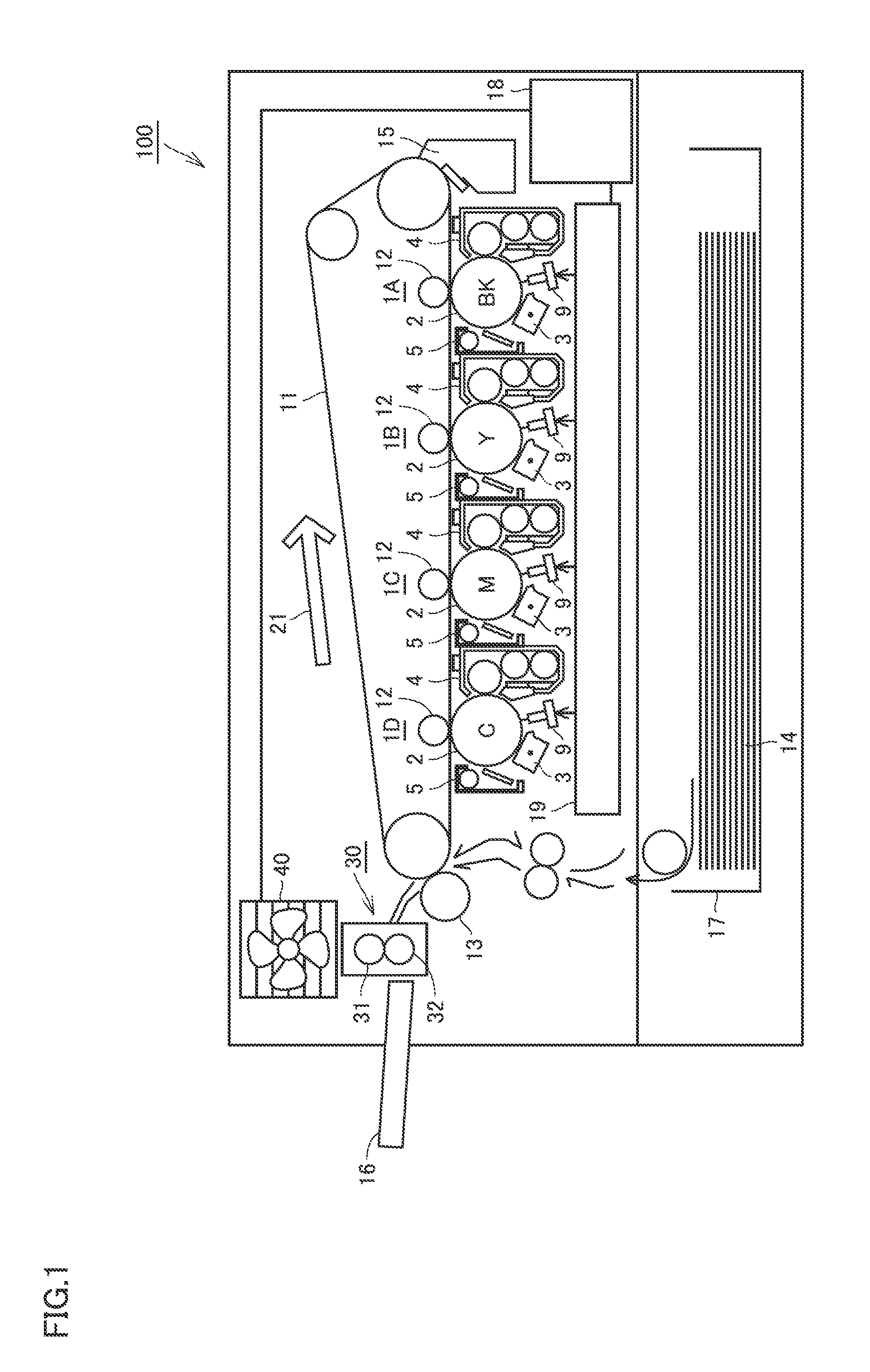
[0036]Referring to FIG. 1, an image forming apparatus 100 according to an embodiment will be described. FIG. 1 is a diagram showing an exemplary apparatus configuration of image forming apparatus 100.

[0037]FIG. 1 shows image forming apparatus 100 as a color printer. Although image forming apparatus 100 as a color printer will be described below, image forming apparatus 100 is not limited to a color printer. For example, image forming apparatus 100 may be a monochrome printer or a multi-functional peripheral (MFP) which is a combination of a monochrome printer or ...


PUM


Abstract

An image forming apparatus has an operating state and a non-operating state with power consumption smaller than in the operating state. The image forming apparatus includes a fixing device for fixing a toner image on a print material by heat, a fan for discharging heat from the image forming apparatus, and a control unit for controlling operation of the fan. When a non-operating time from shifting to the non-operating state to shifting to the operating state is shorter than a predetermined time, the control unit allows the fan to operate with predetermined power in the operating state. When the non-operating time is equal to or longer than the predetermined time, the control unit stops the fan or allows the fan to operate with power smaller than the predetermined power in the operating state.

Description

[0001]This application is based on Japanese Patent Application No. 2015-143957 filed with the Japan Patent Office on Jul. 21, 2015, the entire content of which is hereby incorporated by reference.BACKGROUND OF THE INVENTION[0002]Field of the Invention[0003]The present disclosure relates to control of an image forming apparatus, and more particularly to control of the fan included in an image forming apparatus.[0004]Description of the Related Art[0005]Electrophotographic image forming apparatuses are commonly used. An electrophotographic image forming apparatus includes a fixing device. The fixing device fuses a toner image by heat to fix the toner image on a print material. In connection with a technique for adjusting the temperature for fixing a toner image on a print material, Japanese Laid-Open Patent Publication No. 2012-242635 discloses an image forming apparatus in which “the surface temperature of the heating member can be maintained in STANDBY mode within a range of setting ...

Claims


Application Information

Patent Timeline
IPC IPC(8): G03G15/20G03G21/20
CPCG03G21/206G03G15/2039G03G15/205G03G15/5004G03G2215/0132G03G15/2003G03G15/2064G03G2215/2016
Inventor OTSUKA, YUTAKASAITO, MASASHIMATSUO, RYOHEIKOBAYASHI, TOSHIHITO
Owner KONICA MINOLTA INC
Why Eureka
Try Eureka