
LED lamp fixture having dual side power rail and magnetic coupling

a technology of led lamp fixture and power rail, which is applied in the direction of coupling device connection, lighting support device, lighting and heating apparatus, etc., can solve the problems of not being well optimized for use with led-based modules, tending to be relatively inflexible output, etc., and achieve the effect of convenient module movemen

Active Publication Date: 2017-09-19
MOLEX INC
View PDF19 Cites 23 Cited by
  • Summary
  • Abstract
  • Description
  • Claims
  • Application Information

AI Technical Summary

Benefits of technology

The patent describes a fixture that has a rail with wings that make it look like an I-beam. The fixture also has powered contacts along both upper and lower surfaces of the rail. The fixture also includes modules that can be attached to the rail and powered by the powered contacts. These modules can move along the rail using a side configuration. The rail can have powered contacts on both the top and bottom surfaces. The technical effect of this invention is that it provides a flexible and efficient way to power modules along a rail.

Problems solved by technology

One issue with existing luminaires is that they tend to be relatively inflexible in their output.
This can be accomplished but traditional luminaires were designed and intended to be used with incandescent bulbs and thus are not well optimized for use with LED-based modules.

Method used


Image

  • LED lamp fixture having dual side power rail and magnetic coupling
  • LED lamp fixture having dual side power rail and magnetic coupling
  • LED lamp fixture having dual side power rail and magnetic coupling

Examples


Embodiment Construction

[0020]The detailed description that follows describes exemplary embodiments and is not intended to be limited to the expressly disclosed combination(s). Therefore, unless otherwise noted, features disclosed herein may be combined together to form additional combinations that were not otherwise shown for purposes of brevity.

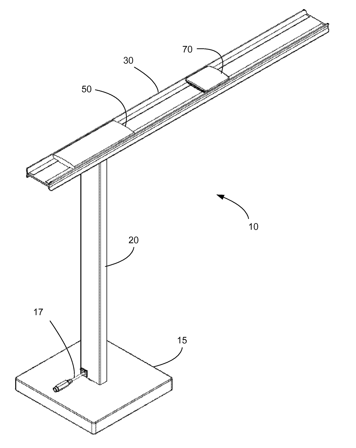
[0021]FIGS. 1-14 illustrate features of a luminaire 10 and an LED module 70 suitable for use therewith, the luminaire configured to use on a desktop. Convention luminaires often include a reflector that helps focus the light downward. As can be appreciated, the depicted LED module 70 can include an internal reflector (and / or lens) to help shape the emitted light and thus the luminaire does not need a reflector. Furthermore, due to the flexibility provided by rail 30, the placement of the LED module 70 can be varied as desired. Furthermore, as the rail has powered contacts 34a, 35a and 34b, 35b on a top surface 36a and bottom surface 36b, respectively, the LED modu...


PUM


Abstract

A luminaire includes a rail, first and second pairs of wings formed at opposed edges of the rail, a pair of contacts on each one of the top and bottom surfaces of the rail, at least one LED module attachable to the rail via at least one magnetic element, such that the LED module is electrically coupled to one pair of the pairs of contacts. The rail configured to receive and power the at least one LED module on either one of the top and bottom surfaces.

Description

RELATED APPLICATIONS[0001]This application claims priority to U.S. Provisional Application No. 61 / 728,615, filed Nov. 20, 2012, which is incorporated herein by reference in its entirety.FIELD OF THE INVENTION[0002]The present invention relates to field of luminaires, more specifically to the field of luminaires suitable for use with LED modules.DESCRIPTION OF RELATED ART[0003]Desktop luminaires are well known and have been used as a way to illuminate an area, typically the area on a desk (or table or the like). One issue with existing luminaires is that they tend to be relatively inflexible in their output. Typically about the most that can be accomplished with an existing luminaire is that it can be dimmed. Light emitting diodes (LED) based light sources have become more popular but most attempts to use LEDs have been based on attempting to package an LED bulb in a traditional luminaire. This can be accomplished but traditional luminaires were designed and intended to be used with ...

Claims


Application Information

Patent Timeline
Patent Type & Authority Patents(United States)
IPC IPC(8): H02G5/02H01R25/14F21V21/35F21V23/00F21V21/096F21S6/00F21Y115/10
CPCF21V21/35F21S6/003F21V21/096F21V23/00F21Y2115/10
Inventor ZADEREJ, VICTORCANZANO, TIMOTHY
Owner MOLEX INC
Learn More