
Liquid gear pump

a technology of gear pump and liquid, which is applied in the direction of positive displacement liquid engine, liquid fuel engine, instruments, etc., can solve the problems of pump not operating efficiently with cold or warm liquid, excessive wear or jamming of gears, etc., and achieve excellent low water absorption capacity, avoid excessive engagement between driving gear and idle gear, and improve mechanical strength

Active Publication Date: 2017-09-19
JOHNSON ELECTRIC SA
View PDF25 Cites 0 Cited by
  • Summary
  • Abstract
  • Description
  • Claims
  • Application Information

AI Technical Summary

Benefits of technology

The patent text describes a sealing device that prevents liquid from leaking out of a pump chamber along a motor shaft. The device uses a shaft seal made of a material called PPS, which has low water absorption capacity and is resistant to high temperatures, acid, and wear and tear. The device is also safe for use with food. The technical effects of this device are improved sealing performance, better protection of the driving gear and idle gear from expansion deformation, and better overall mechanical strength.

Problems solved by technology

As the gears of the gear pump are immersed in the hot liquid, the gears expand creating excessive engagement between the two gears leading to excessive wear or jamming of the gears, neither of which is desired.
This can be avoided by appropriate sizing of the gears to allow for the expansion, however this means that the pump does not operate efficiently with cold or warm liquids.

Method used


Image

  • Liquid gear pump
  • Liquid gear pump
  • Liquid gear pump

Examples


Embodiment Construction

[0030]FIG. 1 is a schematic diagram of an automatic beverage dispenser 10 incorporating a liquid gear pump in accordance with a preferred embodiment of the present invention. The beverage dispenser 10 comprises an user interface 12, which may be a press button, for triggering the dispensing of a beverage, a controller 14 for controlling the dispensing of the beverage, a liquid supply line 16 connecting a liquid source 18 to a liquid gear pump 20 for pumping the liquid from the liquid source 18 to a dispenser point 22 for dispensing the beverage, which may be the liquid itself or a mixture of the liquid and some other beverage material such as coffee powder.

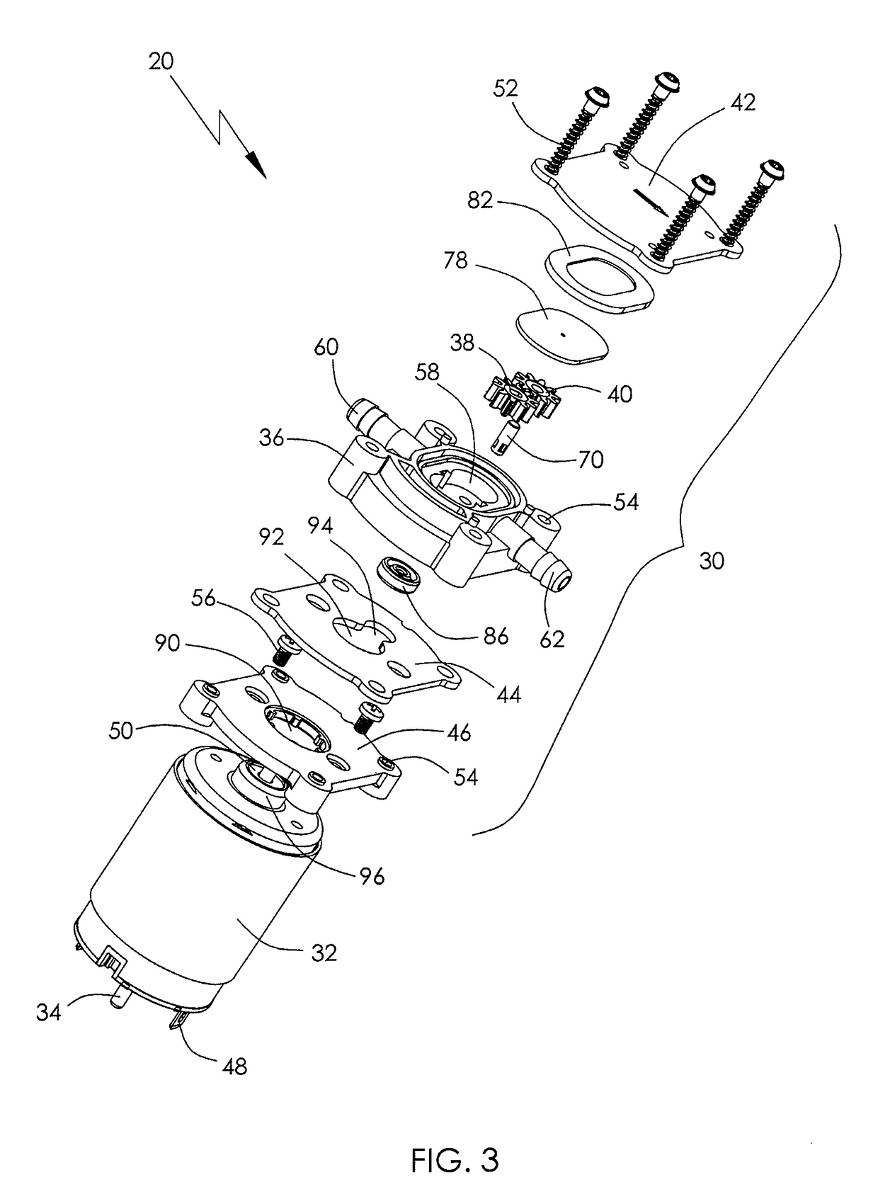
[0031]The gear pump, or parts thereof, is shown in detail in FIGS. 2 to 5. The gear pump 20 comprises a gear pump assembly 30 driven by an electric motor 32. The motor has a motor shaft 34. The gear pump assembly 30 comprises a molded pump housing 36, a driving gear 38 coupled to the motor shaft 34 of the motor 32, an idle gear 40...


PUM


Abstract

A liquid gear pump includes a gear pump assembly and an electric motor with an motor shaft. The gear pump assembly includes a pump housing which defines a pump chamber, an inlet and an outlet which are in fluid communication with the pump chamber, and a driving gear and an idle gear which are received in the pump chamber. The driving gear is driven by the motor shaft. The idle gear is supported on an idle shaft and engaged with the driving gear. The driving gear and the idle gear are made of a material with a main component of PPS.

Description

CROSS REFERENCE TO RELATED APPLICATIONS[0001]This non-provisional patent application claims priority under 35 U.S.C. §119(a) from Patent Application No. 201110146710.1 filed in The People's Republic of China on Jun. 1, 2011.FIELD OF THE INVENTION[0002]This invention relates to a liquid pump and in particular, to a liquid gear pump which is especially suitable for automatic beverage dispensers.BACKGROUND OF THE INVENTION[0003]Gear pumps are popular for precise transfer and metering applications such as automatic beverage dispensers. A typical gear pump includes a pump housing defining a chamber, two gears received in the chamber, and a liquid inlet and a liquid outlet which are in fluid communication with the chamber. One of the two gears is a driving gear driven by a motor and the other one is an idle gear driven by the driving gear. The two gears rotate against each other so as to create the pump action. Liquid entering the pump inlet is drawn into the space between the inner surfa...

Claims


Application Information

Patent Timeline
Patent Type & Authority Patents(United States)
IPC IPC(8): F04C15/00F04C2/08F04C2/18
CPCF04C2/084F04C2/18F04C2/086F04C2220/24F05C2225/00
Inventor KWOK, LO CHINGWU, CHUN FA
Owner JOHNSON ELECTRIC SA
Learn More