
Vehicle employing ordinary and deceleration enhanced drive modes in an accelerator-off state

a technology of acceleration-off state and acceleration mode, which is applied in the field of vehicles, can solve the problems of providing strangeness and not providing significant acceleration of the vehicle, and achieve the effects of relieving the driver's load, and reducing the frequency of returning

Active Publication Date: 2017-09-12
TOYOTA JIDOSHA KK
View PDF52 Cites 3 Cited by
  • Summary
  • Abstract
  • Description
  • Claims
  • Application Information

AI Technical Summary

Benefits of technology

The patent is about a vehicle that can change modes between an ordinary mode and a deceleration enhanced mode. The vehicle can detect the driver's intent to change modes based on their depression of the accelerator, and automatically change from the deceleration enhanced mode to the ordinary mode when the driver releases the accelerator. This change in mode reduces the driver's load and provides better control during deceleration and acceleration. The vehicle can also adjust the deceleration force based on the driver's intent, which improves efficiency and reduces the likelihood of discomfort for the driver. Additionally, the vehicle can use regenerative control and braking mechanisms to generate a high deceleration force during the deceleration enhanced mode. Overall, this patent relieves the driver's load, improves control, and enhances efficiency of the vehicle's deceleration and acceleration capabilities.

Problems solved by technology

Providing the braking position in a shift device and requiring the driver to operate the shift device may thus provide a feeling of strangeness.
This does not provide significant deceleration of the vehicle, in the case of the driver's release of the accelerator after significant depression of the accelerator based on the driver's intention of acceleration.

Method used


Image

  • Vehicle employing ordinary and deceleration enhanced drive modes in an accelerator-off state
  • Vehicle employing ordinary and deceleration enhanced drive modes in an accelerator-off state
  • Vehicle employing ordinary and deceleration enhanced drive modes in an accelerator-off state

Examples


Embodiment Construction

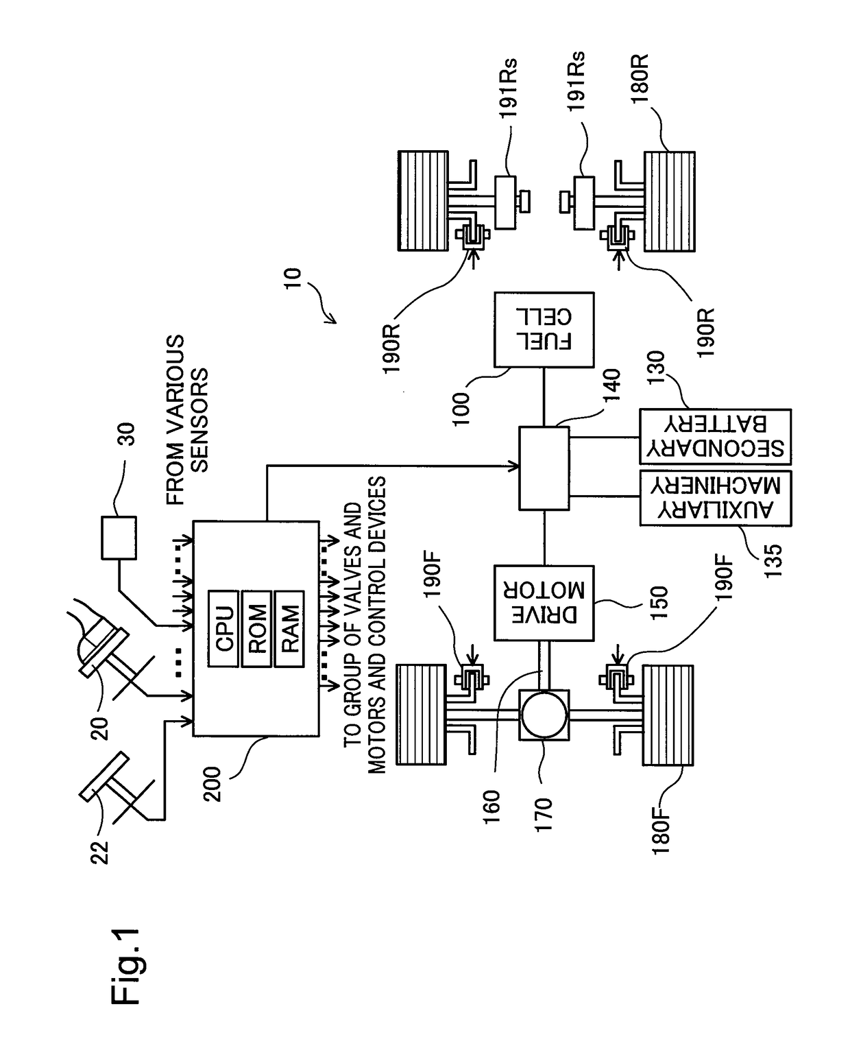
[0022]The following describes an embodiment of the invention with reference to the accompanied drawings. FIG. 1 is a diagram schematically illustrating the configuration of a vehicle 10 according to an embodiment of the invention. The vehicle 10 includes a fuel cell 100, a controller 200, a secondary battery 130, auxiliary machinery 135, a distribution controller 140, a drive motor 150, a driveshaft 160, a distribution gear 170, front wheels 180F, rear wheels 180R, front wheel brakes 190F and rear wheel brakes 190R. The vehicle 10 of the embodiment is a front-wheel drive vehicle, so that the driving force of the drive motor 150 is transmitted from the driveshaft 160 to the front wheels 180F and is more specifically distributed by the distribution gear 170 into the left and right front wheels 180F. The front wheel brakes 190F and the rear wheel brakes 190R are respectively provided on the front wheels 180F and the rear wheels 180R as hydraulically-actuated disk brakes and are control...


PUM


Abstract

A vehicle comprises a fuel cell that is configured to receive supply of a fuel gas and generate electric power and a motor that is configured to be driven with the electric power generated by the fuel cell. The vehicle selectively sets a drive mode of the vehicle in an accelerator-off state between an ordinary mode and a deceleration enhanced mode that decelerates the vehicle with higher deceleration force than deceleration force in the ordinary mode. The vehicle performs regenerative control of the motor in the ordinary mode or performs deceleration control of generating the deceleration force in the deceleration enhanced mode, in order to decelerate the vehicle in the set drive mode. When an accelerator stroke based on a driver's depression of an accelerator becomes higher than a cancellation threshold in the drive mode set to the deceleration enhanced mode, the vehicle changes the drive mode from the deceleration enhanced mode to the ordinary mode.

Description

CROSS-REFERENCE TO RELATED APPLICATIONS[0001]The present application claims priority from Japanese patent application P2014-229942 filed on Nov. 12, 2014, the content of which is hereby incorporated by reference into this application.BACKGROUND[0002]Field[0003]The present invention relates to a vehicle.[0004]Related Art[0005]A fuel cell is mounted, along with a motor, on a vehicle to generate electric power with supply of a fuel gas and supply the generated electric power to the motor linked with an axle of the vehicle. The motor is driven with the electric power generated by the fuel cell, while regenerating electric power under regenerative control to brake the axle. The vehicle is decelerated with the braking force generated by the regenerative control of the motor during a run according to the requirement. Braking by regenerative control is applied mainly in the following two situations:[0006]1) when the driver steps on a brake pedal for the purpose of braking the vehicle;[0007]...

Claims


Application Information

Patent Timeline
Patent Type & Authority Patents(United States)
IPC IPC(8): B60L7/26B60W20/00B60W30/18B60L15/20B60L11/18
CPCB60W30/18127B60L7/26B60L11/1881B60L15/2009B60W2540/10B60W2540/103Y02T10/7005Y02T10/7275B60L2240/12B60L2250/28B60L58/40Y02T10/72Y02T10/64Y02T10/70Y02T90/40
Inventor UMAYAHARA, KENJINADA, MITSUHIRONAKAGAMI, TAKUYA
Owner TOYOTA JIDOSHA KK
Learn More