Flange joint system for SRF cavities utilizing high force spring clamps for low particle generation

a flange joint and high-force spring technology, applied in the direction of electrical equipment, accelerators, etc., can solve the problems of metal-to-metal contact between the threads of the bolt and the threads of the flange, which can produce microscopic contamination particles, and achieve the effect of reducing the generation of particulates

Active Publication Date: 2017-09-05
JEFFERSON SCI ASSOCS LLC
View PDF16 Cites 2 Cited by
  • Summary
  • Abstract
  • Description
  • Claims
  • Application Information

AI Technical Summary

Benefits of technology

[0008]It is therefore an object of the present invention to provide a flange joint system for SRF cavities that will minimize generation of particulates that will negatively affect the performance of the particle accelerator.SUMMARY OF THE INVENTION
[0009]According to the present invention there is provided a flange joint system for SRF cavities. The flange joint system includes a set of high force spring clamps that produce high force on the simple flanges of Superconducting Radio Frequency (SRF) cavities to squeeze conventional metallic seals. The system establishes the required vacuum and RF-tight seal with minimum particle contamination to the inside of the cavity assembly. The spring clamps are designed to stay within their elastic range while being forced open enough to mount over the flange pair. Upon release, the clamps have enough force to plastically deform metallic seal surfaces and continue to a new equilibrium sprung dimension where the flanges remain held against one another with enough preload such that normal handling will not break the seal.

Problems solved by technology

Unfortunately, in the act of assembling the cavities, the metal-to-metal contact between the threads of the bolt and the threads of the flange can produce microscopic contamination particles.
If the dust particles are introduced into the SRF cavities, they can heat up and release electrons that interfere with the particles that are being accelerated by the accelerator, a problem called field emission.

Method used


Image

  • Flange joint system for SRF cavities utilizing high force spring clamps for low particle generation
  • Flange joint system for SRF cavities utilizing high force spring clamps for low particle generation
  • Flange joint system for SRF cavities utilizing high force spring clamps for low particle generation

Examples


Embodiment Construction

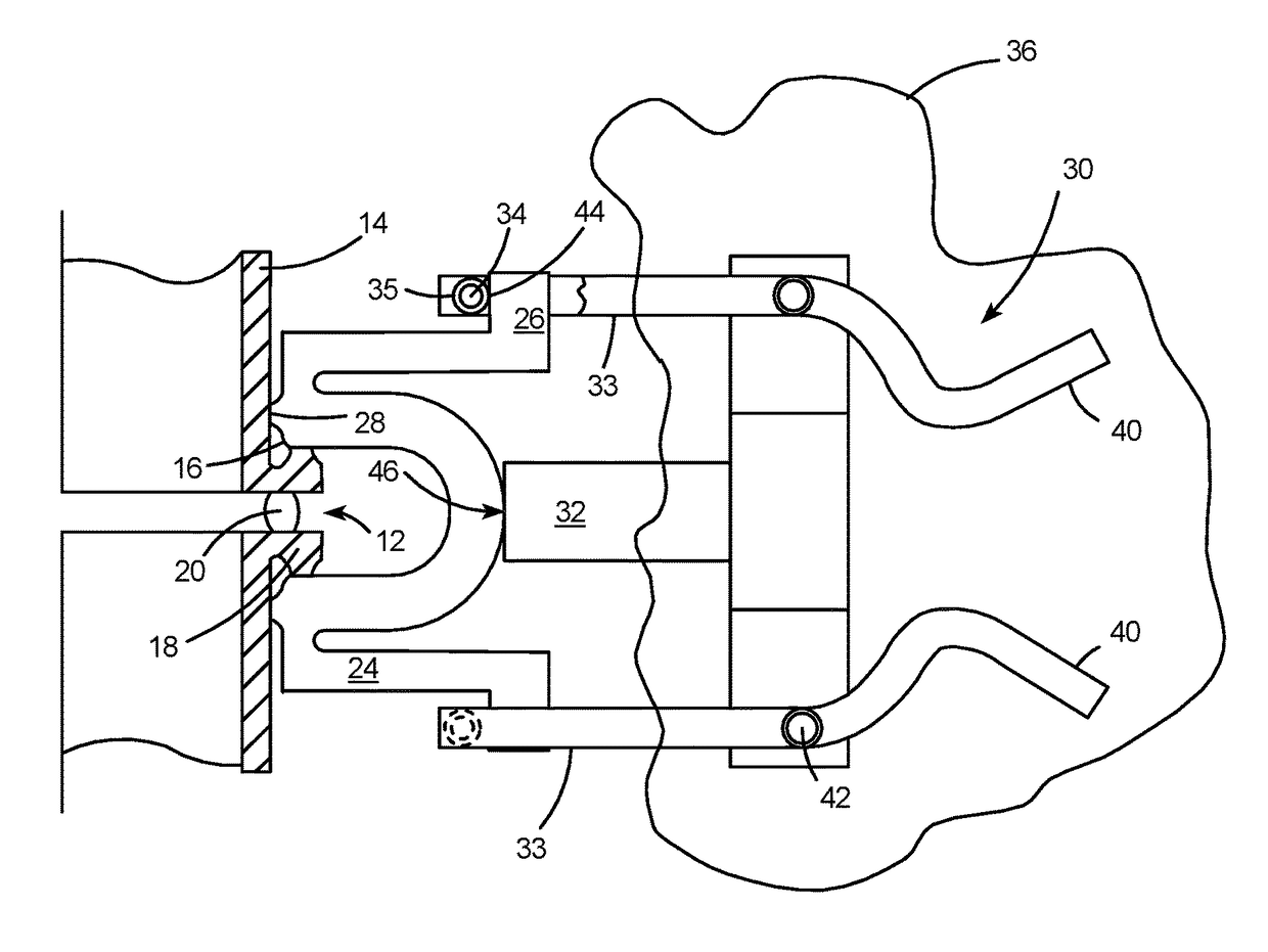
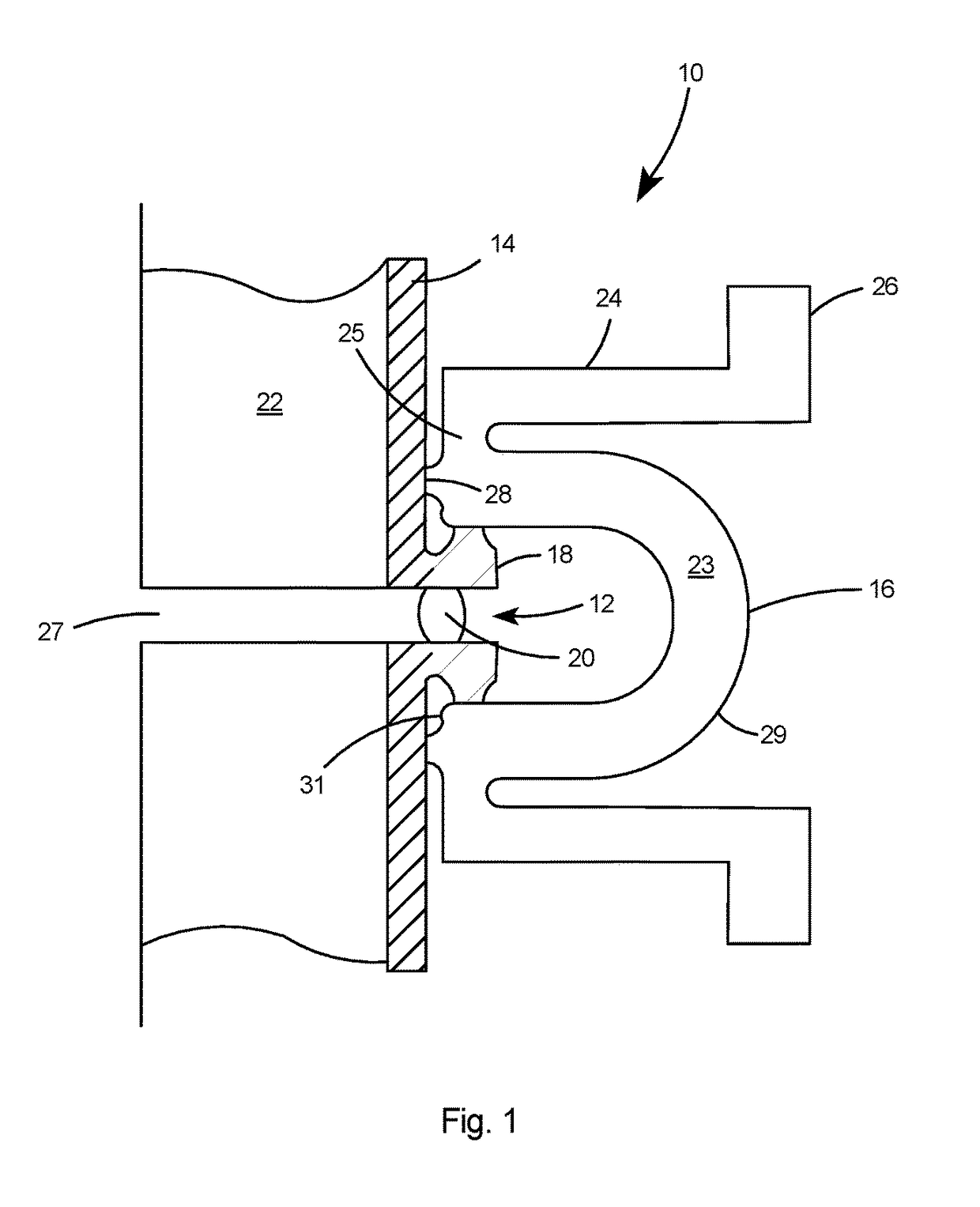
[0016]With reference to FIG. 1 there is shown a first embodiment flange joint system 10 installed on the flange joint 12 of an SRF cavity 14. The flange joint system 10 includes a set of spring clamps 16 that produce high force on the flanges 18 of Superconducting Radio Frequency (SRF) cavities to squeeze a conventional metallic seal 20. The system establishes the required vacuum and RF-tight seal with minimum particle contamination to the inside 22 of the cavity assembly. The spring clamps are designed to stay within their elastic range while being forced open enough to mount over the flange pair. Upon release, the clamps have enough force to plastically deform the surfaces of the metallic seal 20 and continue to a new equilibrium sprung dimension where the flanges remain held against one another with enough preload such that normal handling of the cavity assembly will not break the seal.

[0017]Preferably, the spring clamp 16 is constructed of a material having a high strength, low ...


PUM


Abstract

A flange joint system for SRF cavities. The flange joint system includes a set of high force spring clamps that produce high force on the simple flanges of Superconducting Radio Frequency (SRF) cavities to squeeze conventional metallic seals. The system establishes the required vacuum and RF-tight seal with minimum particle contamination to the inside of the cavity assembly. The spring clamps are designed to stay within their elastic range while being forced open enough to mount over the flange pair. Upon release, the clamps have enough force to plastically deform metallic seal surfaces and continue to a new equilibrium sprung dimension where the flanges remain held against one another with enough preload such that normal handling will not break the seal.

Description

[0001]This application claims the priority of Provisional U.S. patent application Ser. No. 61 / 914,651 filed Dec. 11, 2013.[0002]The United States Government may have certain rights to this invention under Management and Operating Contract No. DE-AC05-06OR23177 from the Department of Energy.FIELD OF THE INVENTION[0003]The present invention relates to Superconducting Radio Frequency (SRF) cavities, and more particularly to a flange joint system for producing an RF-tight seal with minimum particle contamination to the inside of the cavities.BACKGROUND OF THE INVENTION[0004]The Continuous Electron Beam Accelerator Facility (CEBAF) at the Jefferson Lab in Newport News, Virginia, accelerates electrons through SRF cavities that are maintained at Ultra High Vacuum (UHV) or at less than 10−9 torr.[0005]Deformable metal seals are typically used at the interface between the SRF cavities in order to form a vacuum-tight seal. The SRF cavities are typically joined together by installing and torqu...

Claims


Application Information

Patent Timeline
Patent Type & Authority Patents(United States)
IPC IPC(8): H05H7/18H05H7/22H05H7/20
CPCH05H7/18H05H7/20H05H7/22H05H2007/225
Inventor BIALLAS, GEORGE HERMANDALY, EDWARD
Owner JEFFERSON SCI ASSOCS LLC
Why Eureka
Try Eureka