
Hybrid magnetic engine/generator apparatus and method

a hybrid engine and generator technology, applied in the direction of magnetic circuit rotating parts, manufacturing stator/rotor bodies, magnetic circuit shapes/forms/construction, etc., can solve the problems of prior art magnetic engine/generator devices that are not efficient or powerful enough to be truly useful in commercial or individual settings, and achieve the effect of easily overcoming any resistan

Inactive Publication Date: 2017-09-05
MARTELLI JOHN D
View PDF7 Cites 3 Cited by
  • Summary
  • Abstract
  • Description
  • Claims
  • Application Information

AI Technical Summary

Benefits of technology

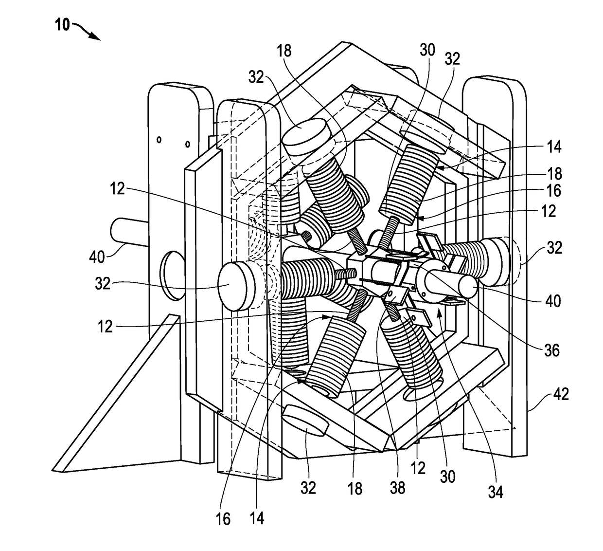
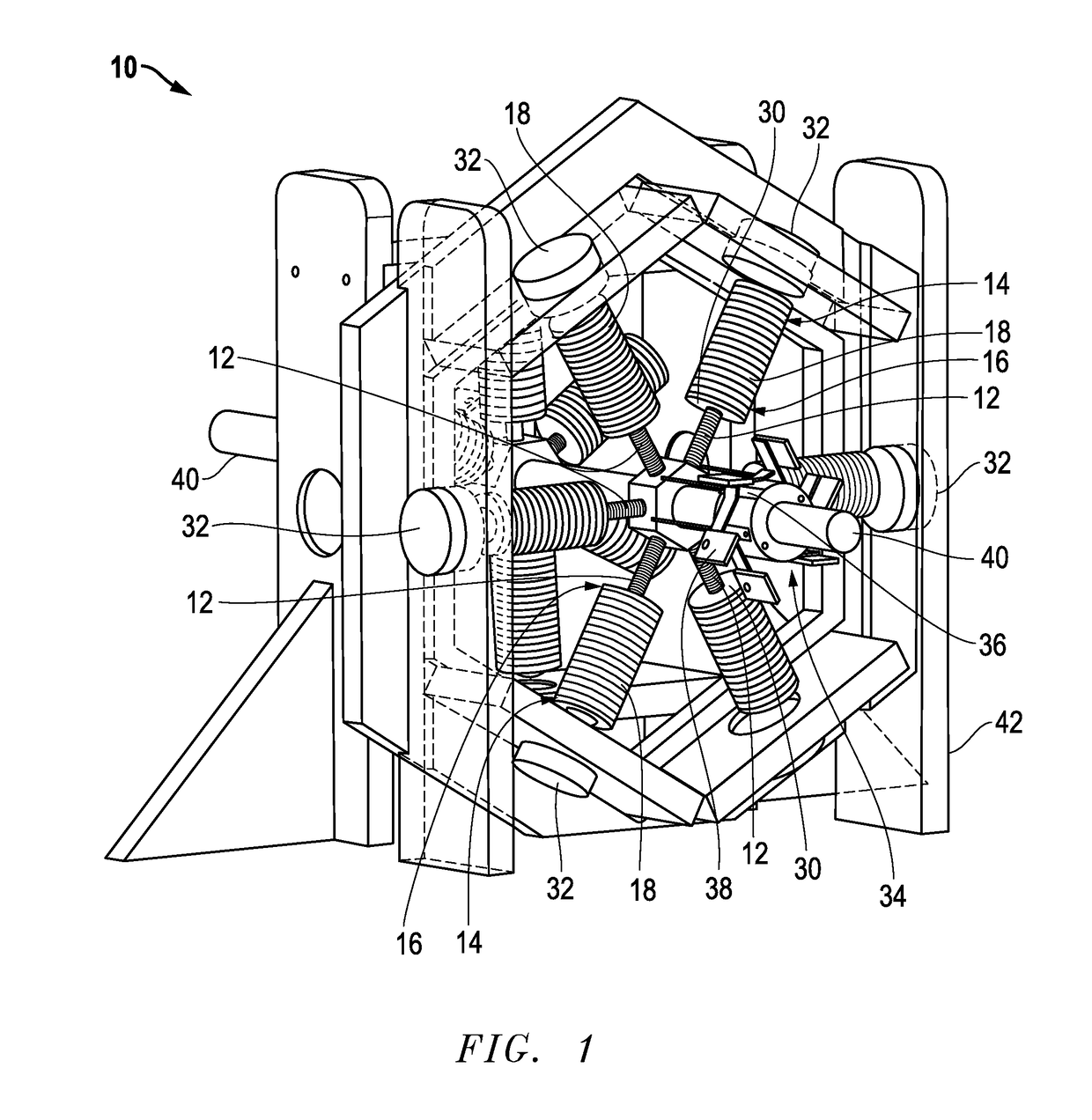
The patent describes a design for a new engine that has non-ferrous metal arms and ferrous metal arms connected to a shaft. The non-ferrous metal arms are positioned oppositely to each other and are connected to the shaft through magnets. This design helps to overcome any resistance on the generator side. The ferrous metal arms are longer than the non-ferrous metal arms. The technical effect of this design is to improve the performance and efficiency of the engine.

Problems solved by technology

A problem exists with regard to the use of magnets in machines used for engines and / or generators.
The problem is that the prior art magnetic engine / generator devices are not efficient enough or powerful enough to be truly useful in either commercial or individual settings.

Method used


Image

  • Hybrid magnetic engine/generator apparatus and method
  • Hybrid magnetic engine/generator apparatus and method
  • Hybrid magnetic engine/generator apparatus and method

Examples


Embodiment Construction

[0027]Before explaining at least one embodiment of the invention in detail, it is to be understood that the invention is not limited in its application to the details of construction and to the arrangements of the components set forth in the following description or illustrated in the drawings. The invention is capable of other embodiments and of being practiced and carried out in various ways. Also, it is to be understood that the phraseology and terminology employed herein are for the purpose of description and should not be regarded as limiting.

[0028]As such, those skilled in the art will appreciate that the conception, upon which this disclosure is based, may readily be utilized as a basis for the designing of other structures, methods and systems for carrying out the several purposes of the present invention. It is important, therefore, that the invention be regarded as including equivalent constructions to those described herein insofar as they do not depart from the spirit an...


PUM


Abstract

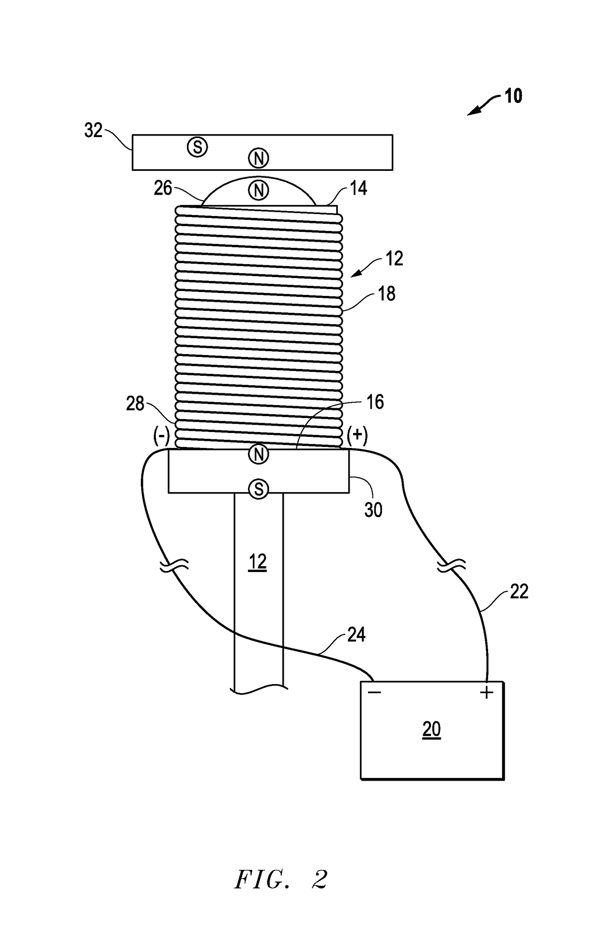
An improved hybrid magnetic engine / generator apparatus and method includes a shaft. A pair of oppositely positioned ferrous metal arms is connected to the shaft where the ferrous metal arms include a first end and a second end. Wire is wrapped in non-overlapping fashion around the ferrous metal arms and the wire includes a positive power connection and a negative power connection. A power source is connected with positive power connection and the negative power connection. A stacking magnet is located at the second end of the ferrous metal arms and an opposing magnet is located opposite from and in proximity to the first end of both of the oppositely positioned ferrous metal arms. A device for selectively connecting with the power source is provided such that the wire is intermittently charged such that polarity at the first end of the ferrous metal arms is intermittently changed.

Description

CROSS REFERENCE TO RELATED APPLICATION[0001]This application claims the benefit of previously filed U.S. provisional patent application No. 61 / 978,386 filed Apr. 11, 2014 for an “Improved Hybrid Magnetic Engine / Generator Apparatus and Method”. The Applicant hereby claims the benefit of this provisional application under 35 U.S.C. §119. The entire content of this provisional application is incorporated herein by this reference.FIELD OF THE INVENTION[0002]This invention relates to an improved magnetic engine / generator device. In particular, in accordance with one embodiment, the invention relates to an improved hybrid magnetic engine / generator apparatus including a shaft. A pair of oppositely positioned ferrous metal arms is connected to the shaft where the ferrous metal arms include a first end and a second end. Wire is wrapped in non-overlapping fashion around the ferrous metal arms and the wire includes a positive power connection and a negative power connection. A power source is ...

Claims


Application Information

Patent Timeline
Patent Type & Authority Patents(United States)
IPC IPC(8): H02K33/00H02K13/00H02K1/24H02K1/17H02K1/22H02K47/04H02K15/03H02K53/00
CPCH02K47/04H02K15/03H02K1/17H02K1/223H02K1/24H02K13/006Y10S74/09H02K53/00H02K23/04H02K23/28H02K23/30H02K23/40H02K47/14H02K99/10H02K99/20
Inventor MARTELLI, JOHN D.
Owner MARTELLI JOHN D
Learn More