Compact bipolarization power splitter, array of a plurality of splitters, compact radiating element and planar antenna comprising such a splitter
a technology of bipolarization and power splitter, which is applied in the direction of polarised antenna unit combination, linear waveguide fed array, antenna, etc., can solve the problems of inability to hybridize waveguide and micro-strip technology, large horn weight, and large weight of antennas, and achieve low loss and high surface efficiency
- Summary
- Abstract
- Description
- Claims
- Application Information
AI Technical Summary
Benefits of technology
Problems solved by technology
Method used
Image
Examples
first embodiment
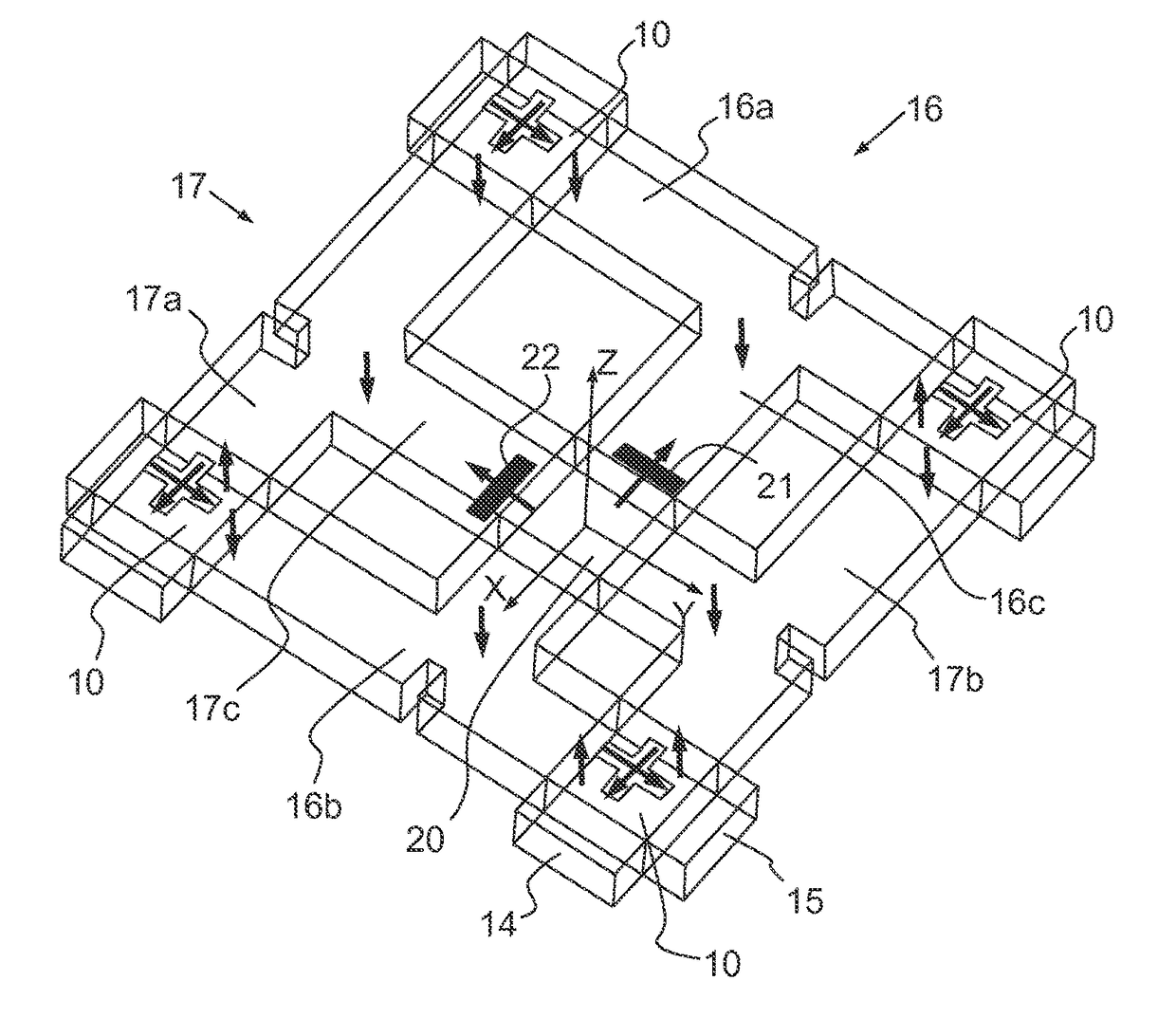
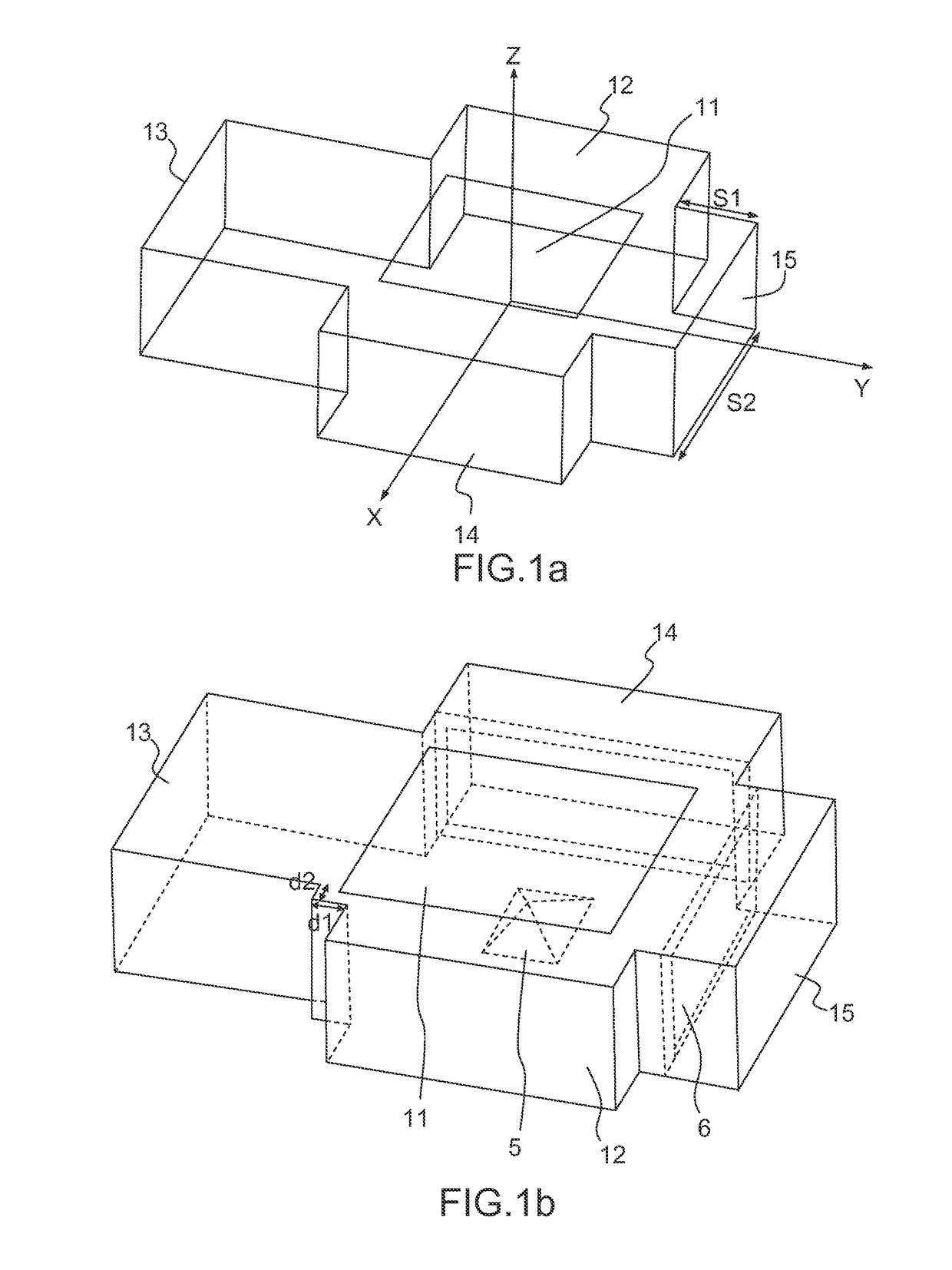
[0062]According to the invention, the two distributors 16, 17 are identical and are mounted perpendicularly in relation to one another in the same plane XY, parallel to the direction of propagation of the waveguides, and their respective transverse branches 16c, 17c intersect in the overlap area. The lateral and transverse waveguides are all mounted flat with their wider peripheral wall parallel to the plane XY and the connections between each lateral waveguide and the transverse waveguide of the lateral and transverse branches of each distributor are implemented by T-couplers in the plane H. The feed of each distributor 16, 17 can be implemented, for example, by two different feed ports connected to a feed source operating in two orthogonal polarizations, the two feed ports being coupled respectively to the distributor by a respective coupling slot 21, 22, disposed in the wall of the corresponding transverse waveguide 16c, 17c and parallel to the plane XY. The two coupling slots 21...
second embodiment
[0063]According to the invention shown in FIGS. 4a and 4b, the two distributors 16, 17 are mounted perpendicularly in relation to one another in the same plane XY, but, in the overlap area, their respective transverse branches 16c, 17c are superimposed one above the other. The superimposition can be implemented either by a curving of the transverse branches, or by a progressive reduction in their cross section as shown in FIG. 4b. Thus, in the bottom view shown in FIG. 4a and the top view shown in FIG. 4b, the transverse branch 16c of the distributor 16 passes below the transverse branch 17c of the distributor 17. The transverse branch 16c, 17c of each distributor is coupled to a respective input port 1, 2 disposed in the lower wall of each corresponding transverse waveguide 16c, 17c, the two input ports 1, 2 of the two transverse branches having orthogonal polarizations. The two transverse branches of the two distributors 16, 17 do not therefore intersect, which allows the coupling...
fourth embodiment
[0065]According to the invention shown in FIGS. 6a, 6b, 6c, the connections between each lateral waveguide and the transverse waveguide of each distributor are implemented by T-couplers in the plane E as in FIGS. 5a and 5b, but the diagram of the lower tier shown in FIG. 6a shows that the coupling slots disposed on the two ends of each transverse waveguide are disposed on two opposite edges of the upper wall of the transverse waveguide. The two transverse waveguide sections located on either side of the intersection area where a central aperture 20 intended for the feed of the distributors is located are not aligned but are offset linearly in relation to one another in a direction perpendicular to the corresponding transverse branch in such a way that the coupling slots 23a, 23b and 24a, 24b respectively, disposed on the opposite edges of each transverse waveguide, are aligned and disposed symmetrically in relation to the central aperture. FIG. 6b is a bottom view showing the config...
PUM
 Abstract
Description
Claims
Application Information
 - R&D
- Intellectual Property
- Life Sciences
- Materials
- Tech Scout
- Unparalleled Data Quality
- Higher Quality Content
- 60% Fewer Hallucinations
Browse by: Latest US Patents, China's latest patents, Technical Efficacy Thesaurus, Application Domain, Technology Topic, Popular Technical Reports.
© 2025 PatSnap. All rights reserved.Legal|Privacy policy|Modern Slavery Act Transparency Statement|Sitemap|About US| Contact US: help@patsnap.com


