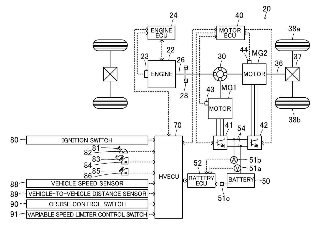
[0007]The disclosure provides a hybrid vehicle that can restrain a driver from developing a feeling of strangeness during the performance of cruise control or variable speed limiter control.
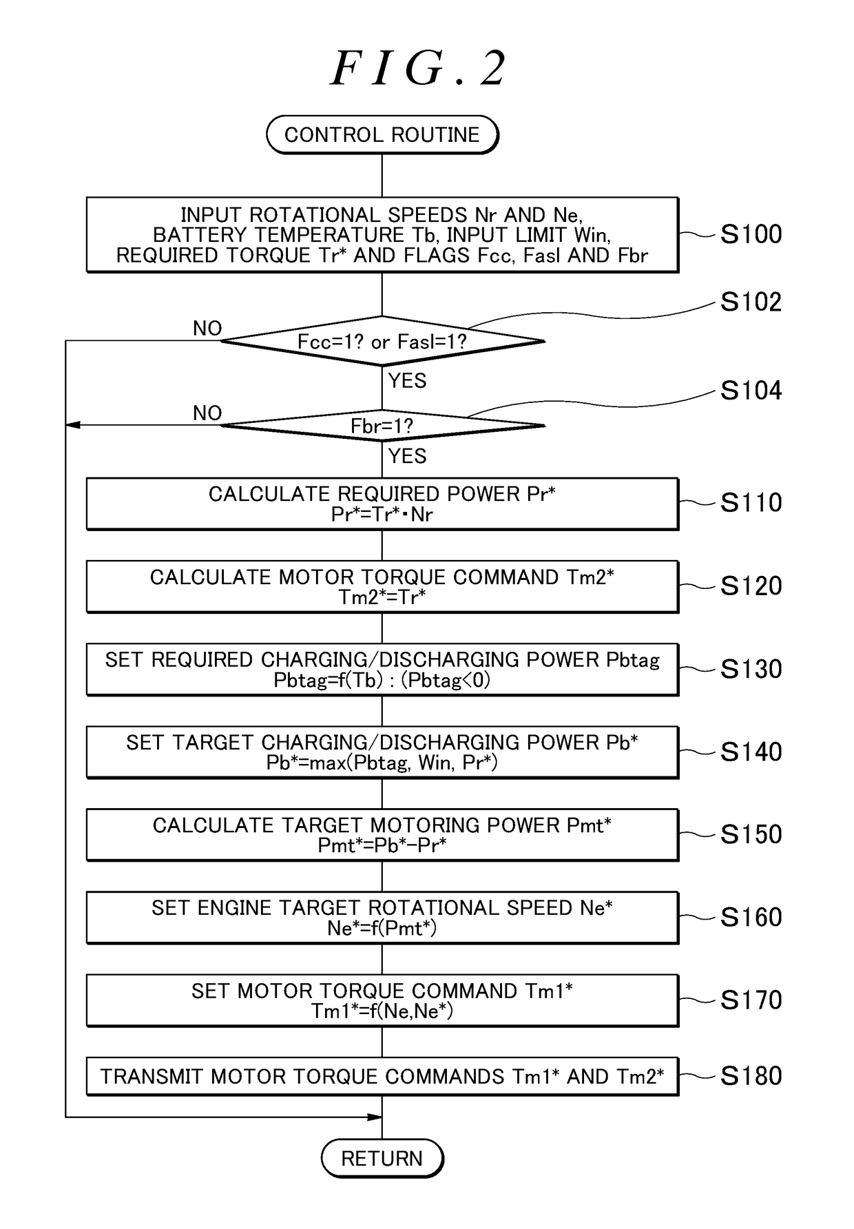
[0009]In the aforementioned aspect of the disclosure, the engine, the first motor and the second motor are controlled such that the vehicle runs while the battery is charged / discharged within the ranges of the permissible charging power and the permissible discharging power respectively. Then, the permissible charging power is set such that the time from the start of the charge of the battery to the start of rapid decrease in the charging power of the battery becomes shorter and the amount of decrease per unit time at the time of the start of rapid decrease in the charging power becomes larger when the charging power is large than when the charging power is small, in the case where the charge is continued. It should be noted herein that “rapid decrease” means that the amount of decrease per unit time is larger than a predetermined amount of decrease. Then, control is performed such that the motoring of the engine is carried out at a higher rotational speed when the required braking force is large than when the required braking force is small, from the start of the charge of the battery to the start of rapid decrease in the charging power, in the case where predetermined control is performed to control the first motor and the second motor such that the battery is charged within the range of the permissible charging power through regenerative driving of the second motor and the motoring of the engine by the first motor with fuel injection stopped and that the required braking force at the braking request is applied to the vehicle, in response to the making of the braking request during the performance of cruise control or variable speed limiter control. Thus, when the required braking force is relatively large, the power consumed by the first motor is made larger and the charging power of the battery is made smaller than in the case where control is performed such that the motoring of the engine is performed at a uniform rotational speed regardless of the required braking force, from the start of the charge to the start of rapid decrease in the charging power. Accordingly, the time to the start of rapid decrease in the charging power of the battery can be restrained from becoming short, and the time to the start of rapid increase in the rotational speed of the engine can be restrained from becoming short. Besides, the amount of decrease per unit time at the time of the start of rapid decrease in the charging power of the battery can also be restrained from becoming large, and the amount of rise per unit time at the time of the start of rapid rise in the rotational speed of the engine can also be restrained from becoming large. As a result, the driver can be restrained from developing a feeling of strangeness when the braking request continues during the performance of cruise control or variable speed limiter control.
[0011]In the aforementioned aspect of the disclosure, the setting unit may be configured to set the permissible charging power such that the time from start of the charge to start of rapid decrease in the charging power becomes shorter when a temperature of the battery is low than when the temperature of the battery is high, in the case where the charge is continued. The control unit may be configured to perform control such that motoring of the engine is carried out at a rotational speed that is higher when the required braking force is large than when the required braking force is small and that is higher when the temperature of the battery is low than when the temperature of the battery is high, until start of rapid decrease in the charging power, in performing the predetermined control in response to the making of the braking request during performance of the cruise control or the variable speed limiter control. Thus, the driver can be more appropriately restrained from developing a feeling of strangeness in accordance with the temperature of the battery, when the braking request continues during the performance of cruise control or variable speed limiter control.
[0012]In the aforementioned configuration, the control unit may be configured to set a required charging power of the battery such that the required charging power becomes smaller when the temperature of the battery is low than when the temperature of the battery is high, until start of rapid decrease in the charging power, in performing the predetermined control in response to the making of the braking request during performance of the cruise control or the variable speed limiter control, limit the required charging power by the permissible charging power and set a target charging power of the battery, set a target rotational speed of the engine such that the target rotational speed becomes higher when the required braking force is large than when the required braking force is small and higher when the target charging power is small than when the target charging power is large, and perform control such that motoring of the engine is carried out at the target rotational speed. Thus, the driver can be restrained from developing a feeling of strangeness when the braking request continues during the performance of cruise control or variable speed limiter control, by setting the required charging power in accordance with the temperature of the battery, setting the target charging power in accordance therewith, and setting the target rotational speed in accordance with the required braking force and the target charging power.


