
Mobile apparatus

a mobile apparatus and apparatus technology, applied in the field of mobile apparatuses, can solve the problems of increasing the influence of body movement noise, unable to measure, superimposed noise on the output signal of the biosensor, etc., and achieve the effect of reducing the body movement noise generated by body movement at the time of operating the mobile apparatus with a finger

Active Publication Date: 2017-08-22
MURATA MFG CO LTD
View PDF53 Cites 9 Cited by
  • Summary
  • Abstract
  • Description
  • Claims
  • Application Information

AI Technical Summary

Benefits of technology

This invention provides a mobile device that reduces noise caused by moving the device while using it with a finger. The device uses a biosensor to obtain a biosignal, which is the result of the movement of the body. This technology aims to make it easier to get accurate readings from the biosensor while using the device.

Problems solved by technology

However, even when a biosensor is provided at a position with which the hand of a user is in contact while the user is operating a mobile apparatus such as a cellular phone, during actual operations, a portion other than a finger used for the operations will also move together with the finger, thereby causing a problem in that noise is superimposed on the output signal of the biosensor.
In particular, when a measured portion is a portion of a hand which performs the operation, noise superimposed on the sensor output signal may become larger than a biosignal, thereby making the measurement impossible.
In addition, when a pulse rate and a heartbeat are measured, obtaining of data in real time or obtaining of continuous data over a relatively long time (for example, about ten seconds to several minutes) is required in many cases, thereby causing an increase in the influence of body movement noise.

Method used


Image

  • Mobile apparatus
  • Mobile apparatus
  • Mobile apparatus

Examples


first embodiment

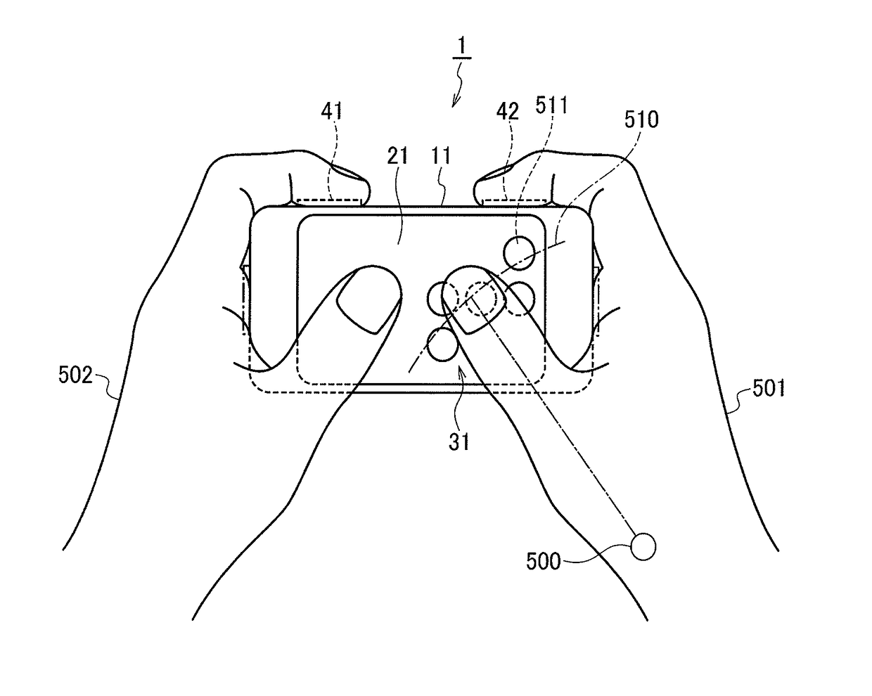
[0044]First, referring to FIG. 1 as well as FIG. 2, the configuration of a mobile apparatus 1 according to a first embodiment will be described. FIG. 1 is a block diagram illustrating the configuration of the mobile apparatus 1. FIG. 2 is a diagram illustrating the arrangement of operation switches at the time when a biosignal is obtained.

[0045]The mobile apparatus 1 is an electronic apparatus which is used (operated) while held in a hand, for example, a cellular phone, a smart phone, a mobile PC such as a tablet PC, a mobile apparatus such as a handheld game console, a remote controller, or the like. Specifically, the mobile apparatus 1 is an electronic apparatus which is held in a hand and the switches thereof are operated with a thumb, for example. Note that a smart phone will be described as an example of the mobile apparatus 1 in the present embodiment (hereinafter, a mobile apparatus is also called a “smart phone”).

[0046]The smart phone 1 includes biosignal sensing units (corr...

second embodiment

[0068]Next, referring to FIG. 4, the configuration of a smart phone (mobile apparatus) 2 according to a second embodiment will be described. FIG. 4 is a block diagram illustrating the configuration of the smart phone 2. Note that in FIG. 4, components that are the same as or equivalent to those of the first embodiment are denoted by the same reference symbols.

[0069]As described above, the position of the carpometacarpal joint 500 of the hand performing operations and the circular arc 510 of a virtual circle whose center is located at the carpometacarpal joint 500 and whose radius is the distance from the carpometacarpal joint 500 to the tip of the thumb, are set in advance on the basis of stochastic data such as the standard size of a hand, the standard lengths of fingers, and a standard manner in which the smart phone 1 is held. However, the optimum arrangement of the switches varies in accordance with, for example, the size of a user's hand or the way the user holds the apparatus....

third embodiment

[0080]Next, referring to FIG. 7 as well as FIG. 8, the configuration of a smart phone (mobile apparatus) 3 according to a third embodiment will be described. FIG. 7 is a block diagram illustrating the configuration of the smart phone 3. FIG. 8 is a diagram illustrating the arrangement of the operation switches of the smart phone 3 at the time when photoelectric pulse wave signals are obtained. Note that in FIGS. 7 and 8, components that are the same as or equivalent to those of the first embodiment are denoted by the same reference symbols.

[0081]Compared with the smart phone 1 described above, the smart phone 3 has an additional function of switching between the photoelectric pulse wave sensing units 41 and 42 that read detection signals in accordance with the frequency of operations of the operation switches 31 performed by the right hand 501 and the frequency of operations of the operation switches 32 performed by the left hand 502. Hence, the smart phone 3 includes a signal proce...


PUM


Abstract

A smart phone includes photoelectric pulse wave sensing units that obtain photoelectric pulse wave signals from hands holding the smart phone, a touch screen on which a plurality of operation switches that accept operations performed by thumbs are displayed, and a switch arrangement changing unit that changes the arrangement of the displayed plurality of operation switches. The switch arrangement changing unit, when photoelectric pulse wave signals are obtained by the photoelectric pulse wave sensing units, changes the arrangement of the operation switches displayed on the touch screen in such a manner that the operation switches are arranged along a circular arc of a virtual circle whose center is located at a carpometacarpal joint of the thumb of a right hand performing operations and whose radius is the distance from the carpometacarpal joint to the tip of the thumb.

Description

CROSS REFERENCE TO RELATED APPLICATIONS[0001]The present application is a continuation of International Application No. PCT / JP2012 / 003224, filed May 17, 2012, which claims priority to Japanese Patent Application No. 2011-140571, filed Jun. 24, 2011, the entire contents of each of which are incorporated herein by reference.FIELD OF THE INVENTION[0002]The present invention relates to mobile apparatuses and specifically to mobile apparatuses including a biosensor for obtaining biosignals.BACKGROUND OF THE INVENTION[0003]In recent years, people have been increasingly interested in maintaining or improving their health. Hence, it is desired that one can more easily obtain biological information such as a pulse rate and an electrocardiogram in a daily life for health management. Patent Document 1 discloses a cellular phone that can detect biological information in the normal process of using the phone. Further, Patent Document 2 discloses a cellular phone that allows a user to measure bio...

Claims


Application Information

Patent Timeline
Patent Type & Authority Patents(United States)
IPC IPC(8): G06F3/02G06F3/0488H04M1/725A61B5/00G06F3/041A61B5/1455A61B5/01A61B5/0205A61B5/0402A61B5/0488A61B5/07G06F3/048H04M1/72454
CPCH04M1/72569A61B5/6898G06F3/04883A61B5/01A61B5/0205A61B5/0402A61B5/0488A61B5/07A61B5/1455A61B5/4266A61B5/4872G06F3/0412G06F3/0416H04M2250/22G06F21/51A61B5/318A61B5/389H04M1/72454A61B5/024A61B5/7207
Inventor SHIMUTA, TORU
Owner MURATA MFG CO LTD
Learn More