
Connector

a technology of connecting parts and connectors, applied in the field of connecting parts, can solve the problems of difficult deformation of the locking surface and the lock projection locked state, and achieve the effect of enhancing the holding force of the receiving-side component for holding the fitting-side component in the fitting state and reducing the difficulty of deformation

Active Publication Date: 2017-08-22
SUMITOMO WIRING SYST LTD
View PDF4 Cites 1 Cited by
  • Summary
  • Abstract
  • Description
  • Claims
  • Application Information

AI Technical Summary

Benefits of technology

The present invention provides a receptacle with a lock receiving portion that can securely hold a fitting-side component. The receptacle is shaped to match the profile of the fitting-side component, making it compact. The lock receiving portion has two walls that bridge each other, reducing the likelihood of opening deformation. The lock projection has an inclined surface that allows for easy fitting of the fitting-side component. The receiving-side component has reinforcing portions that make it difficult to deform and enhance the holding force for holding the fitting-side component. The lock projection is designed to be difficult to displace, improving overall operability.

Problems solved by technology

Since the lock projection is difficult to displace, a locked state of the lock projection and the locking surface is not easily released.

Method used


Image

  • Connector
  • Connector
  • Connector

Examples


Embodiment Construction

[0032]Hereinafter, one specific embodiment of the invention is described in detail with reference to FIGS. 1 to 13.

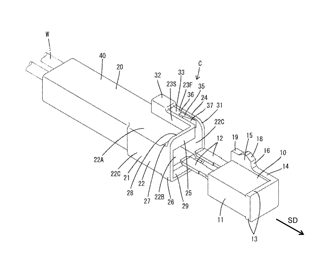
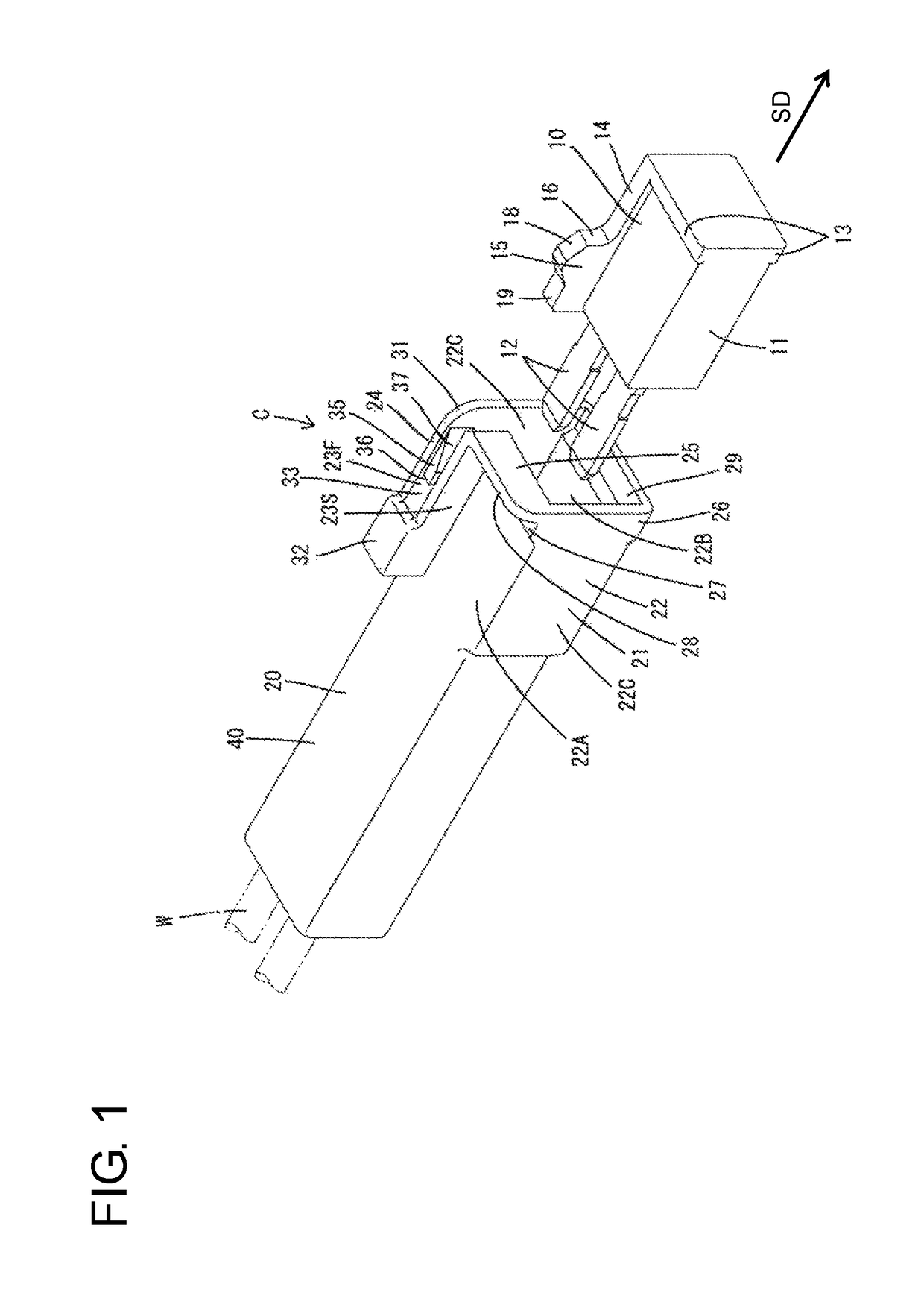
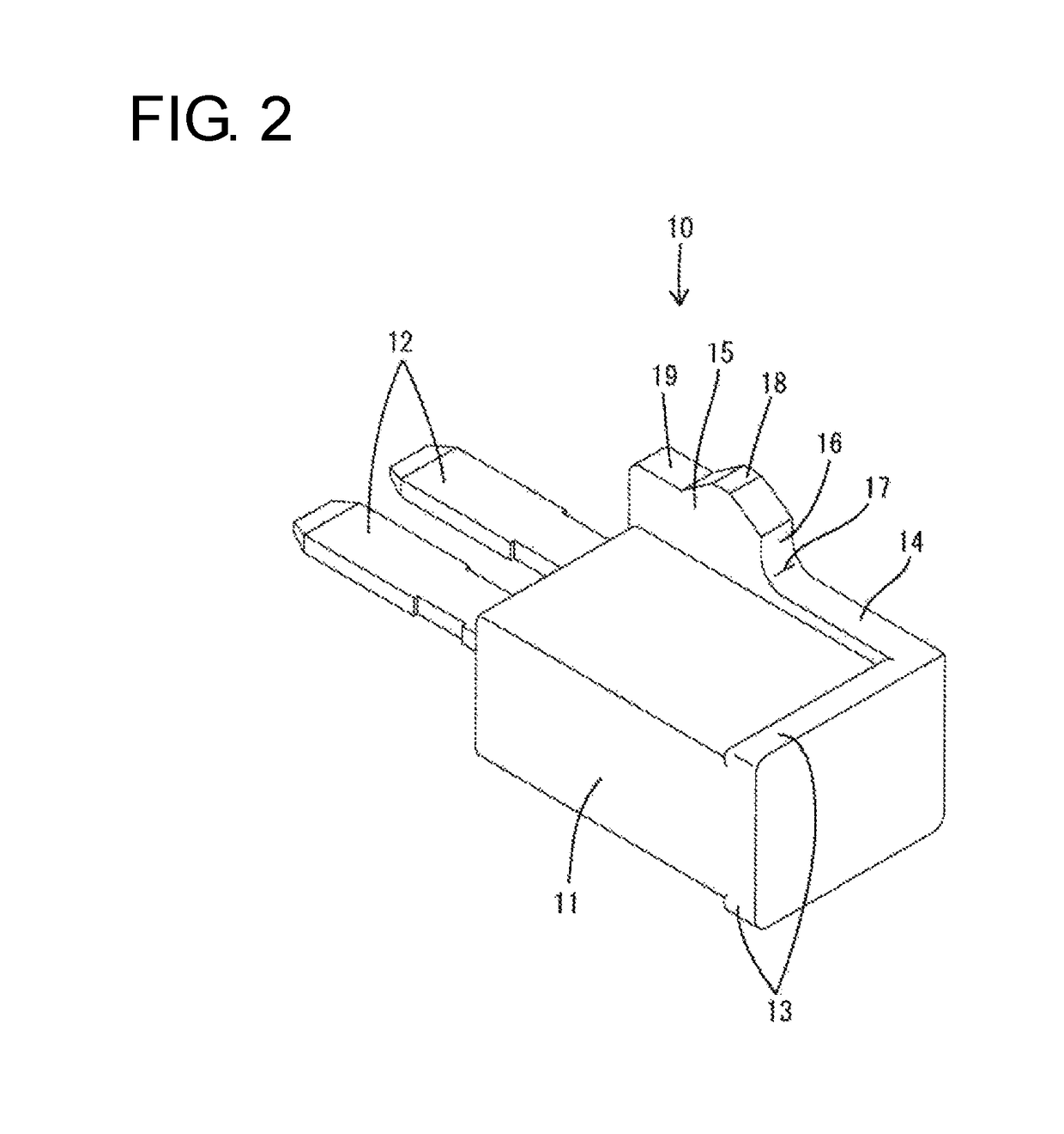
[0033]A connector C in this embodiment is a small-size connector with a built-in large-capacity chip diode (not shown) and is used to provide a rectifying action. The connector C includes a fitting-side component 10 in which the chip diode is built and a receiving-side component 20 to which the fitting-side component 10 is to be fit. In the following description, in each constituent member, a front side in a connecting direction to a mating side is referred to as a front side, and an opposite side thereof (separating direction) is referred to as a rear side. Specifically, a left upper side of FIG. 1 is a front side and a right lower side is a rear side in the fitting-side component 10 and a right lower side of FIG. 1 is a front side and a left upper side is a rear side in the receiving-side component 20. Further, upper and lower sides of FIG. 1 are referred to as upper ...


PUM


Abstract

A connector is configured such that a fitting-side component (10) is fit into a receiving-side component (20). The fitting-side component (10) includes a block-shaped main body (11) and a lock (15) standing on an outer surface of the main body (11). The receiving-side component (20) includes a receptacle (21) open forward and externally fittable to the fitting-side component (10). A locking surface (16) is provided on a surface of the lock (15) facing an opening side of the receptacle (21) in a fitted state of the fitting-side component (10) and the receiving-side component (20). The locking surface (16) stands substantially at a right angle to a separating direction from the receiving-side component (20). The receiving-side component (20) includes a lock projection (35) projecting on an inner surface of the receptacle (21) for locking the locking surface 16 from the opening side of the receptacle (21).

Description

BACKGROUND[0001]1. Field of the Invention[0002]The invention relates to a connector.[0003]2. Description of the Related Art[0004]Conventionally, there is known a connector configured such that a block-shaped fitting-side component is fit into a receiving-side component. The receiving-side component includes a receptacle externally fittable to the fitting-side component. For example, Japanese Unexamined Patent Publication No. 2011-187302 discloses a connector in which a block-shaped diode connector is fit in a connector housing. This connector includes a projecting portion that projects slightly out of the receptacle of the connector housing as a locking structure for holding the diode connector fit in the connector housing. The projecting portion has a vertical wall standing up outward from the receptacle and a horizontal wall projecting in a substantially perpendicular direction from the tip of the vertical wall. The projecting portion is provided on an opening end side of the rece...

Claims


Application Information

Patent Timeline
Patent Type & Authority Patents(United States)
IPC IPC(8): H01R13/627H01L23/00H01R13/11H01R13/66H01R103/00
CPCH01R13/6272H01L24/40H01R13/113H01R13/6641H01R2103/00H01R33/05H01L2924/00014H01L2224/37599H01L24/37H01L2224/37099H01L2224/84
Inventor MATSUURA, JUNYA
Owner SUMITOMO WIRING SYST LTD
Learn More