
Positioning device for glass substrate

a technology of positioning device and glass substrate, which is applied in the direction of conveyor parts, electric devices, transportation and packaging, etc., can solve the problems of large transmission error, increase production cost of setting the positioning mechanism on the machine, and high cost of positioning mechanism, so as to improve the production yield of tft-lcd, accurately transfer, and reduce the transmission error of glass substra

Active Publication Date: 2017-08-22
TCL CHINA STAR OPTOELECTRONICS TECH CO LTD
View PDF20 Cites 2 Cited by
  • Summary
  • Abstract
  • Description
  • Claims
  • Application Information

AI Technical Summary

Benefits of technology

The present invention provides a positioning device for accurately positioning glass substrates before special processes in LCD manufacturing facilities. The device reduces transferring errors of the glass substrate and accurately transfers it to a machine for the special process, resulting in improved production yield of TFT-LCD. The device includes a gear group driving the conveying belt and positioning mechanisms.

Problems solved by technology

This transfer method is simple and easy to control, but the transmission error is large, especially in fast delivery or long-distance transmission.
However, it is expensive to set a positioning mechanism on the machine, due to complexity of the structure and electronic systems of the machine.
Therefore, it brings increase of production cost to set the positioning mechanism on the machine.
Furthermore, the positioning effect of the positioning mechanism for the glass substrate is not entirely wishful, which results of reduction of production yield of the TFT-LCD.

Method used


Image

  • Positioning device for glass substrate
  • Positioning device for glass substrate
  • Positioning device for glass substrate

Examples


Embodiment Construction

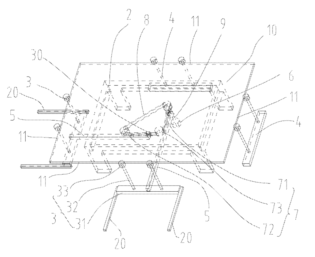
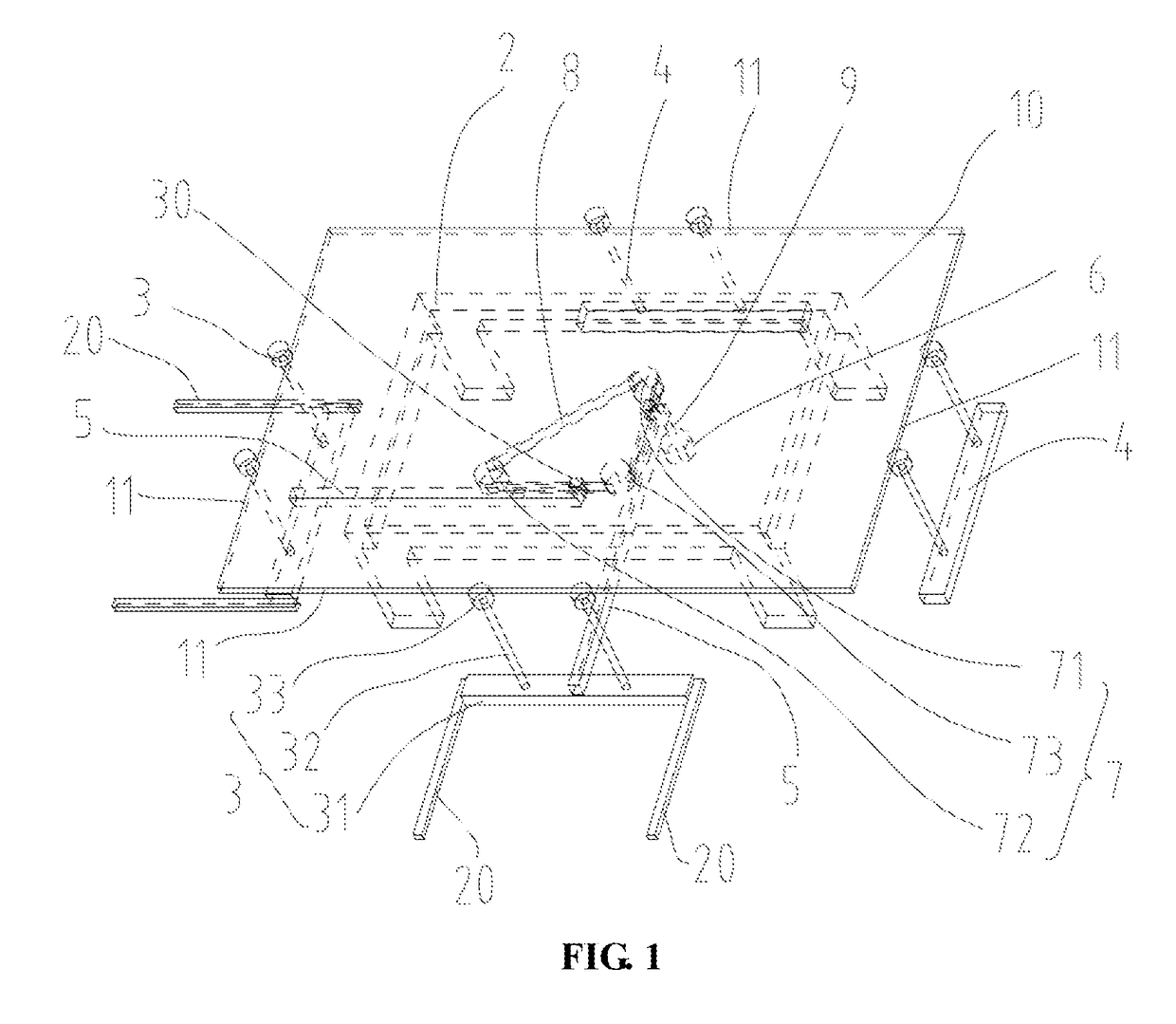
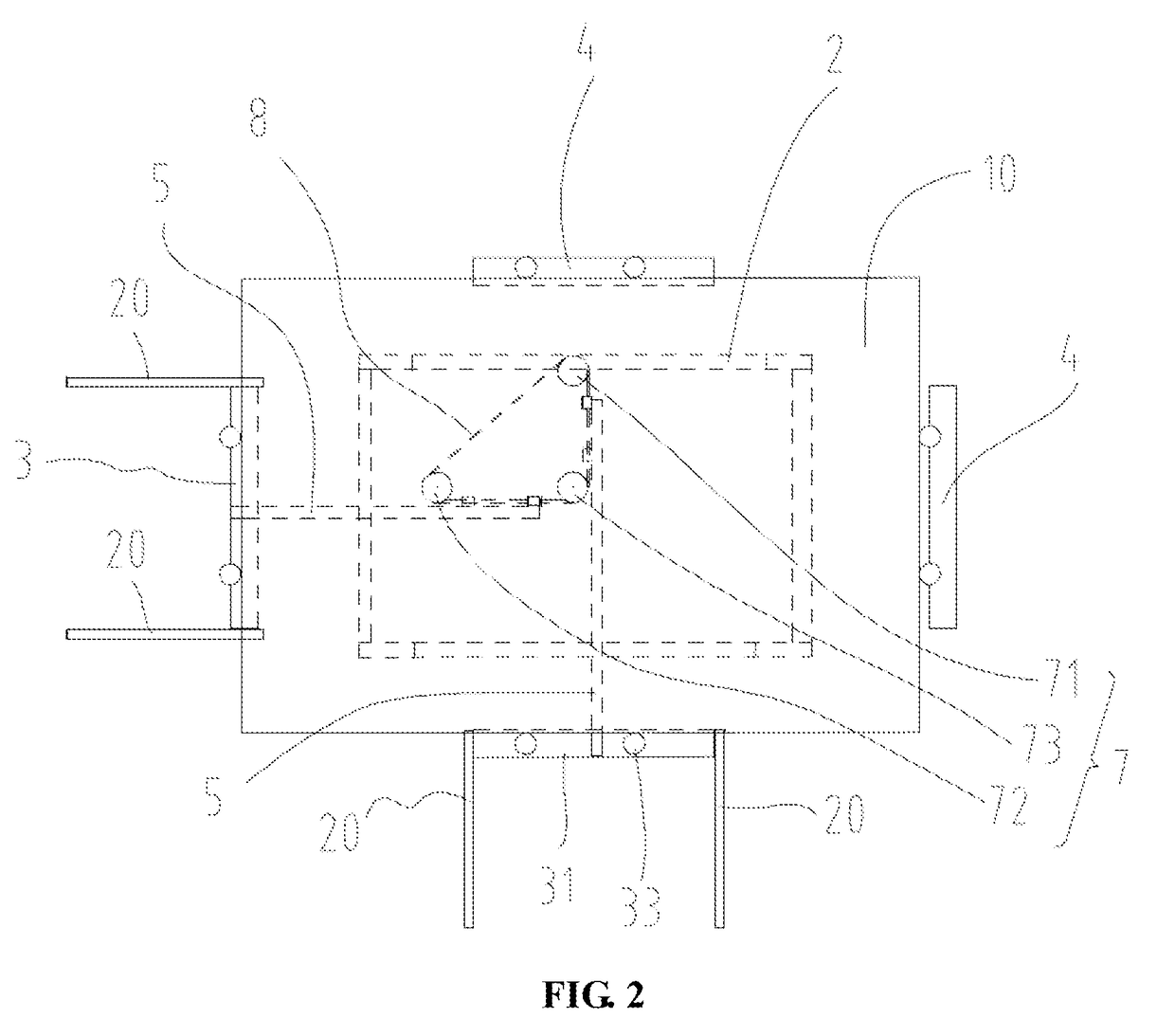
[0019]Please refer to FIG. 1 and FIG. 2, the present invention provides a positioning device, configured to position a glass substrate 10. The glass substrate 10 comprises two pairs of opposite sides 11. In this embodiment, the glass substrate 10 is used to manufacture a thin film transistor-liquid crystal display (TFT-LCD).

[0020]In the embodiment, the positioning device is configured in an automated production line, and is provided to position the glass substrate 10 of the TFT-LCD before a special process that requires an accuracy position for the glass substrate 10.

[0021]The positioning device comprises a supporting base 2, a pair of first positioning mechanisms 3, a pair of second positioning mechanisms 4, a pair of connecting bars 5, a driving member 6, a gear group 7 and a conveying belt 8.

[0022]The supporting base 2 is configured for supporting the glass substrate 10. The pair of first positioning mechanisms 3 are located on two neighboring sides 11 of the two pairs of opposit...


PUM


Abstract

The present invention provides a positioning device configured to position a glass substrate. The positioning device comprises a support base, a pair of first positioning mechanisms located on two neighboring sides of the glass substrate, a pair of second positioning mechanisms located on another two neighboring sides of the glass substrate, respectively, a pair of connecting bars, a driving member, a gear group and a conveying belt sleeved on the gear group. One end of the one of the pair of connecting bar is fixed with the conveying belt, and another end is fixed with one of the pair of first positioning mechanisms. One end of another one of the pair of connecting bar is fixed with the conveying belt, and another end is fixed with another one of the pair of first positioning mechanisms.

Description

FIELD OF THE INVENTION[0001]The present invention relates to mechanical field, and more particularly to a positioning device for a glass substrate.BACKGROUND OF THE INVENTION[0002]Typically, a glass substrate of a thin film transistor -liquid crystal display (TFT-LCD) is transferred by a robot in an automated production line of an LCD manufacturing facility. This transfer method is simple and easy to control, but the transmission error is large, especially in fast delivery or long-distance transmission. In an existing production line, the glass substrate is required to be positioned accurately in a machine for special processes, so as to process the glass substrate accurately. However, it is expensive to set a positioning mechanism on the machine, due to complexity of the structure and electronic systems of the machine. Therefore, it brings increase of production cost to set the positioning mechanism on the machine. Furthermore, the positioning effect of the positioning mechanism fo...

Claims


Application Information

Patent Timeline
Patent Type & Authority Patents(United States)
IPC IPC(8): H01L21/677H01L21/68H01L21/687
CPCH01L21/67796H01L21/68H01L21/68721H01L21/68728B65G49/063H01L21/67721
Inventor JIANG, YUNSHAOLIN, KUN HSIENWANG, YONGQIANGQI, MINGHUCHEN, ZENGHONGYANG, WEIBINGSHU, ZHIYOUYANG, GUOKUNLI, CHENYANGZI
Owner TCL CHINA STAR OPTOELECTRONICS TECH CO LTD
Learn More