
Distributed MU-MIMO channel estimation algorithm and transmission method in LoRa uplink system

A channel estimation and distributed technology, applied in channel estimation, baseband systems, transmission systems, etc., to reduce transmission errors and improve robustness

Pending Publication Date: 2022-01-11
NORTHWEST UNIV(CN)
View PDF3 Cites 2 Cited by
  • Summary
  • Abstract
  • Description
  • Claims
  • Application Information

AI Technical Summary

Problems solved by technology

[0005] In view of the deficiencies in the prior art, the purpose of the present invention is to provide a distributed MU-MIMO channel estimation algorithm in the LoRa uplink system to solve the problem that the MU-MIMO channel has not been implemented in the LoRa network with the same frequency and asynchronous transmission in the prior art. Technical Issues of MIMO Transmission

Method used


Image

  • Distributed MU-MIMO channel estimation algorithm and transmission method in LoRa uplink system
  • Distributed MU-MIMO channel estimation algorithm and transmission method in LoRa uplink system
  • Distributed MU-MIMO channel estimation algorithm and transmission method in LoRa uplink system

Examples


Embodiment 1

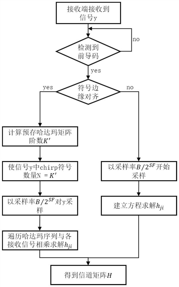
[0107] This embodiment provides a distributed MU-MIMO channel estimation algorithm in a LoRa uplink system, such as figure 1 shown, including the following steps:

[0108] Step 1, when the signal y transmitted by K nodes arrives at the receiving end at the same time, since the K nodes are all new nodes joining the system, there are K·R channels h ji Unknown; transmitting 1 symbol will generate K R unknowns and R equations, so the encoding matrix used is at least K+1 order;

[0109] Among them, in the first equation of the R equations, the data received by the first receiving antenna is:

[0110] the y 1 (n') = h 11 the s 1 (n′)+…+h 1i the s K (n') Formula 12;

[0111] In other equations in the R equations, the expression of the data received by the receiving antenna is deduced in turn on the basis of formula 12;

[0112] j represents the jth receiving antenna;

[0113] i represents the i-th node;

[0114] h ji Indicates the channel from the i-th node to the j-th rec...

Embodiment 2

[0149] This embodiment provides a multi-node MU-MIMO transmission method in a LoRa uplink system, such as figure 2 shown, including the following steps:

[0150] Step 1, using multiple nodes to send signals to the gateway, the signals of different nodes are transmitted through the Rayleigh fading channel, and all signals and noise are combined to reach the receiving antenna;

[0151] Step 2, for the signal obtained in step 1, it is first necessary to detect the preamble;

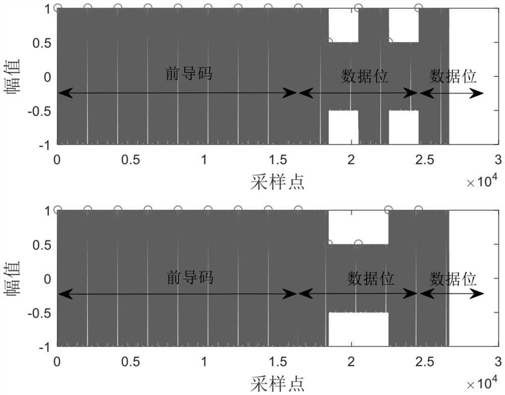
[0152] The preamble is the basis for detecting the signal at the receiving end. After the preamble is detected, the channel estimation can be performed. Therefore, detecting the preamble is a prerequisite for LoRa to enable MU-MIMO;

[0153] Step 3, the receiving end performs distributed MU-MIMO channel estimation to obtain channel information;

[0154] The method for the distributed MU-MIMO channel estimation adopts the distributed MU-MIMO channel estimation algorithm in the LoRa uplink system in embodimen...


PUM


Abstract

The invention provides a distributed MU-MIMO channel estimation algorithm and a transmission method in a LoRa uplink system, and the method comprises the steps: when signals y transmitted by K nodes arrive at a receiving end at the same time, enabling the receiving end to firstly detect a lead code in the received signals, and after the lead code is detected, continuously detecting whether symbol edges of different nodes are aligned or not; when symbol edges are aligned, calculating a pre-stored Hadamard matrix order K', enabling the chiirp symbol number N in the signal y to be equal to K', sampling the signal y at a sampling rate B / 2SF, traversing a Hadamard sequence, and multiplying the Hadamard sequence by each signal to solve hji; when symbol edges are not aligned, starting the sampling at a sampling rate B / 2SF, and establishing an equation to solve hji. The number of unknown numbers in a transmission equation is reduced through a special sampling rate, a method for solving channel information is provided based on a Hadamard sequence, and mixed signals are separated by adopting a channel equalization algorithm after the channel information is acquired, so that the problem of realizing MU-MIMO transmission in the same-frequency asynchronous transmission LoRa network is solved.

Description

technical field [0001] The invention belongs to the technical field of wireless communication, relates to a LoRa uplink system, in particular to a distributed MU-MIMO channel estimation algorithm in the LoRa uplink system. Background technique [0002] In order to improve the overall throughput of the LoRa system and make full use of frequency band resources, due to the limitation of commercial gateways, one demodulator can only demodulate one channel of data, and only one SF can be used for transmission on the same frequency, which greatly wastes frequency band resources , which limits the transmission throughput and transmission efficiency. The existing method achieves concurrent decoding by combining time-domain features, which increases the system throughput to three times that of LoRaWAN; there are also methods that use cumulative spectral coefficients to distinguish conflicting signals without time offsets, but require conflicting signals to have different powers. Alt...

Claims


Application Information

Patent Timeline
Patent Type & Authority Applications(China)
IPC IPC(8): H04B7/0452H04L25/02
CPCH04B7/0452H04L25/024H04L25/0242Y02D30/70
Inventor 牛进平张李郭艺杨香李艳艳王薇房鼎益
Owner NORTHWEST UNIV(CN)
Learn More