Eureka AIR delivers breakthrough ideas for toughest innovation challenges, trusted by R&D personnel around the world.

Ergonomic head mounted display device and optical system

a display device and ergonomic technology, applied in the field of optical system, can solve the problems of thin design and compromise the tir condition of some reflective surfaces, and achieve the effect of superior optical performan

Active Publication Date: 2017-08-22
MAGIC LEAP INC
View PDF27 Cites 412 Cited by
  • Summary
  • Abstract
  • Description
  • Claims
  • Application Information

AI Technical Summary

Benefits of technology

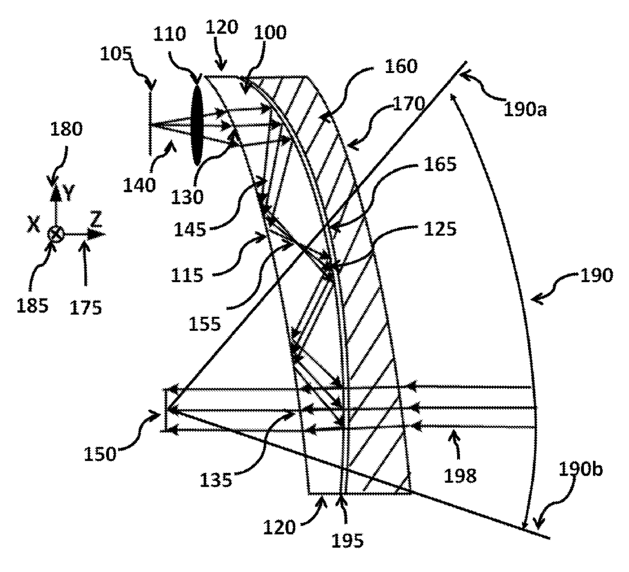
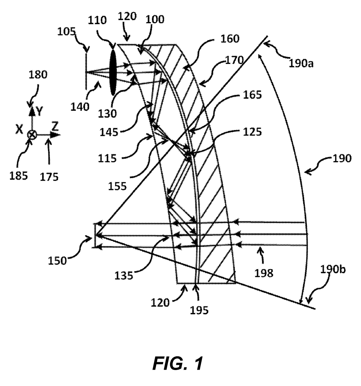
[0006]This application concerns an ergonomic optical see-through head mounted display (OST-HMD) device with an eyeglass-form appearance and freeform optical systems for use as an optical viewing device in such display devices. The optical viewing device in an OST-HMD typically provides an optical path for viewing a displayed virtual image and a see-through path for directly viewing a real-world scene. The virtual image path may include a miniature image display unit to supply display content and an ergonomically-shaped display viewing optics through which a user views a magnified image of the displayed content. The display viewing optics includes a light guiding device (referred to hereafter as a freeform waveguide prism) containing multiple freeform refractive and reflective surfaces. The display viewing optics may also include additional coupling optics to properly inject light from the image display device into the waveguide prism. The location and shape of the freeform surfaces and the coupling optics are sized, dimensioned, positioned and / or oriented such that a viewer is able to see a clear, magnified image of the displayed content. The see-through path of the head-mounted display device is provided by the waveguide prism and a freeform see-through compensation lens positioned (e.g., attached to) outwardly of an exterior surface of the prism. The see-through compensation lens, contains multiple freeform refractive surfaces, and enables proper viewing of the surrounding environment across a very wide see-through field of view. The waveguide prism and the see-through compensation lens are sized, dimensioned, positioned and / or oriented to ergonomically fit with the ergonomic factors of the human heads enabling a wrap-around design of a lightweight, compact, and see-through display system which has an eyeglass-form appearance, wide see-through field of view, and superior optical performance.
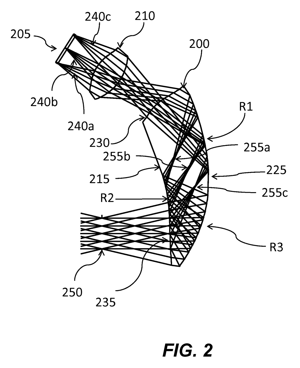
[0007]Various embodiments of freeform optical systems for use as an optical viewing device in an ergonomic head mounted display device are described herein. At least some of the freeform optical systems described herein are optimized to provide ergonomically shaped viewing optics that fit with the ergonomic factors of the human head, allowing them to be wrapped around a human face and present an eyeglass-like appearance instead of helmet-like appearance in prior HMD designs. Various embodiments also offer a see-through capability, allowing a user to view the surrounding environment through the viewing optics, as well as the displayed content on an image display device. At least some embodiments offer a see-through FOV that may be considerably larger than the FOV of the virtual view.

Problems solved by technology

Such thin designs may compromise the TIR condition on some of the reflective surfaces.

Method used


Image

  • Ergonomic head mounted display device and optical system
  • Ergonomic head mounted display device and optical system
  • Ergonomic head mounted display device and optical system

Examples


Embodiment Construction

[0021]Various embodiments according to the present invention will be fully described with respect to the attached drawings. The descriptions are set forth in order to provide an understanding of the invention. However, it will be apparent that the invention can be practiced without these details. Furthermore, the present invention may be implemented in various forms. However, the embodiments of the present invention described below shall not be construed as limited to the embodiments set forth herein. Rather, these embodiments, drawings and examples are illustrative and are meant to avoid obscuring the invention.

[0022]The various embodiments generally relate to ergonomically designed freeform optical systems for use as an optical viewing device in optical see-through HMDs with an eyeglass-form appearance and a wide see-through field of view (FOV). FIG. 1 shows an optical system in the form of an image display system which projects displayed virtual images into the user's eye pupil t...


PUM

PropertyMeasurementUnit
thicknessaaaaaaaaaa
thicknessaaaaaaaaaa
thicknessaaaaaaaaaa

Abstract

Optical systems such as image display systems include a freeform optical waveguide prism and a freeform compensation lens spaced therefrom by a gap of air or index cement. The compensation lens corrects for aberrations which the optical waveguide prism will introduce in light or images from an ambient real-world environment. The optical waveguide prism receives actively projected images at an entry location, and emits the projected images at an exit location after internally reflecting the images along an optical path therein. The image display system may include an image source and coupling optics. The approach permits design of an optical viewing device, for example in optical see-through HMDs, achieving an eyeglass-form appearance and a wide see-through field of view (FOV).

Description

BACKGROUND[0001]Technical Field[0002]The present application relates generally to an optical see-through head-mounted display (OST-HMD) device, and more particularly, to ergonomically designed freeform optical systems for use as an optical viewing device in optical see-through HMDs with an eyeglass-form appearance and a wide see-through field of view (FOV).[0003]Description of the Related Art[0004]Head-mounted displays (HMD) have long been proven invaluable for many applications, spanning the fields of scientific visualization, medicine and military training, engineering design and prototyping, tele-manipulation and tele-presence, and personal entertainment systems. In mixed and augmented reality systems, optical see-through HMDs are one of the basic approaches to combining computer-generated virtual scene with the views of a real-world scene. Typically through an optical combiner, an OST-HMD optically overlays computer-generated images onto the real-world view while maintaining a d...

Claims


Application Information

Patent Timeline
Patent Type & Authority Patents(United States)
IPC IPC(8): G02B27/14G02B27/00G02B27/01H04N7/00G02F1/1335G09G5/00G02B27/10G03H1/00
CPCG02B27/0172G02B27/0025G02B2027/011G02B2027/0123
Inventor GAO, CHUNYU
Owner MAGIC LEAP INC
Why Eureka
Eureka Blog
Learn More