Bumper absorber attachment structure

a technology of absorber and absorber, which is applied in the direction of bumpers, vehicle components, vehicular safety arrangments, etc., can solve the problems of insufficient reaction force of the absorber, difficult processing to provide the receiving jig at the length direction center portion, and difficult processing to provide the first engaged portion and the second engaged portion at the vehicle width direction center portion. , to achieve the effect of suppressing a gap, reducing processing difficulty, and facilitating application

Active Publication Date: 2017-08-22
TOYOTA JIDOSHA KK
View PDF5 Cites 0 Cited by
  • Summary
  • Abstract
  • Description
  • Claims
  • Application Information

AI Technical Summary

Benefits of technology

[0006]When collision load is input to the bumper absorber during a vehicle-to-vehicle collision, such as a minor collision, or a collision with a pedestrian, the bumper absorber transfers collision load to the bumper reinforcement and bears reaction force from the bumper reinforcement, and so undergoes compression deformation toward the vehicle rear side along the vehicle front-rear direction. Collision energy can be absorbed by this compression deformation of the bumper absorber. Since the thinned portion is formed to the bumper absorber, the bumper absorber itself is more liable to undergo compression deformation, enabling collision load borne by the pedestrian in a collision with a pedestrian to be reduced.

Problems solved by technology

However, there is a possibility that the collision load acts so as to displace the bumper absorber toward the vehicle lower side due to an input position of the collision load to the bumper absorber.
Thus, when the bumper absorber attempts to be displaced toward the vehicle lower side, there is a possibility that the lower leg is displaced toward the vehicle lower side originating at the thinned portion with respect to the upper leg that is engaged and does not move, and so no longer abuts the bumper reinforcement.
When the lower leg no longer abuts the bumper reinforcement, there is a possibility that the bumper absorber cannot bear sufficient reaction force from the bumper reinforcement, and that the bumper absorber does not undergo compression deformation.
However, in cases of an elongated shaped extrusion molded component such as the bumper reinforcement, it would be difficult to provide the receiving jig at a length direction center portion, such that processing to provide the first engaged portion and the second engaged portion at the vehicle width direction center portion would be difficult.
If there was a gap between the bumper absorber and the bumper reinforcement, there would be a possibility that the bumper absorber repeatedly abuts and moves away from the bumper reinforcement due to vibration of the vehicle or the like, causing a chattering noise to occur.

Method used


Image

  • Bumper absorber attachment structure
  • Bumper absorber attachment structure
  • Bumper absorber attachment structure

Examples


first exemplary embodiment

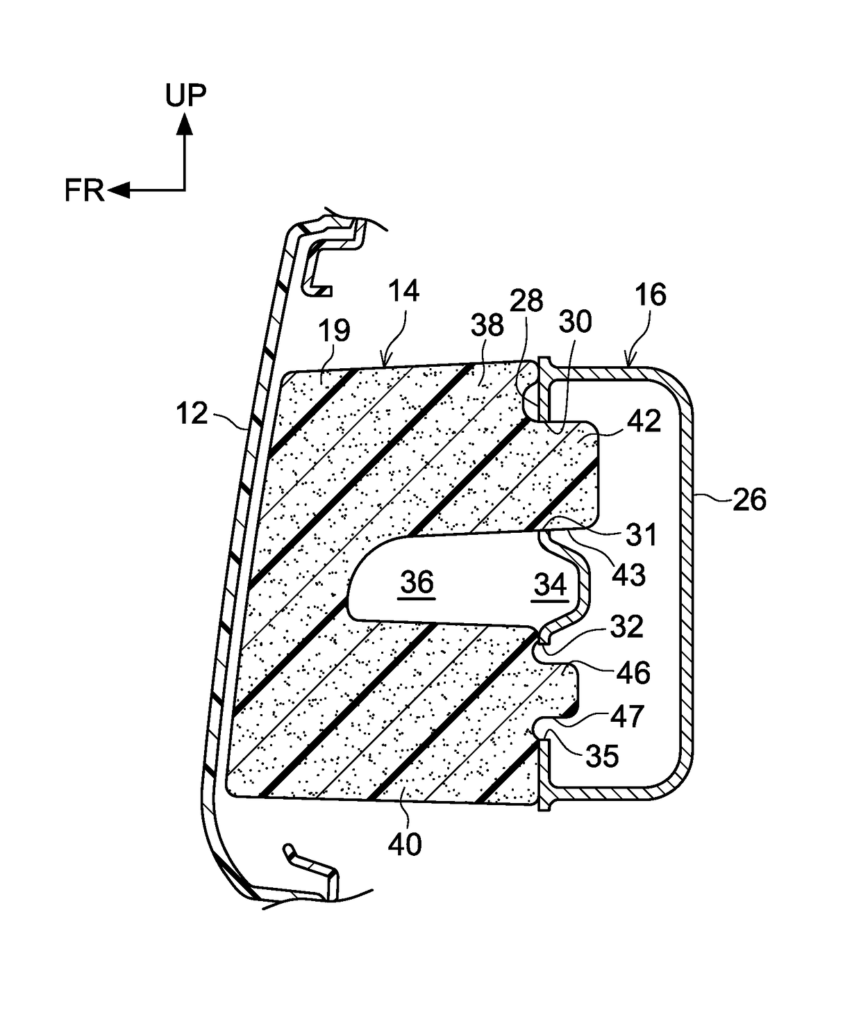
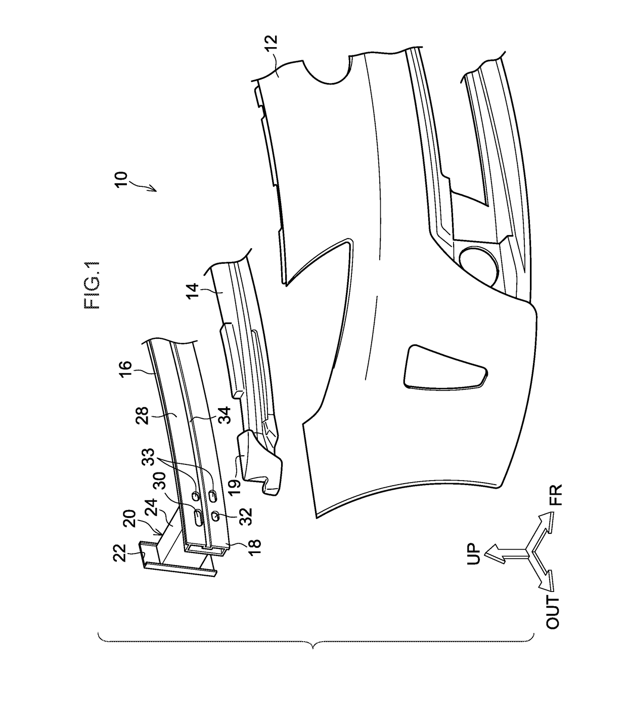
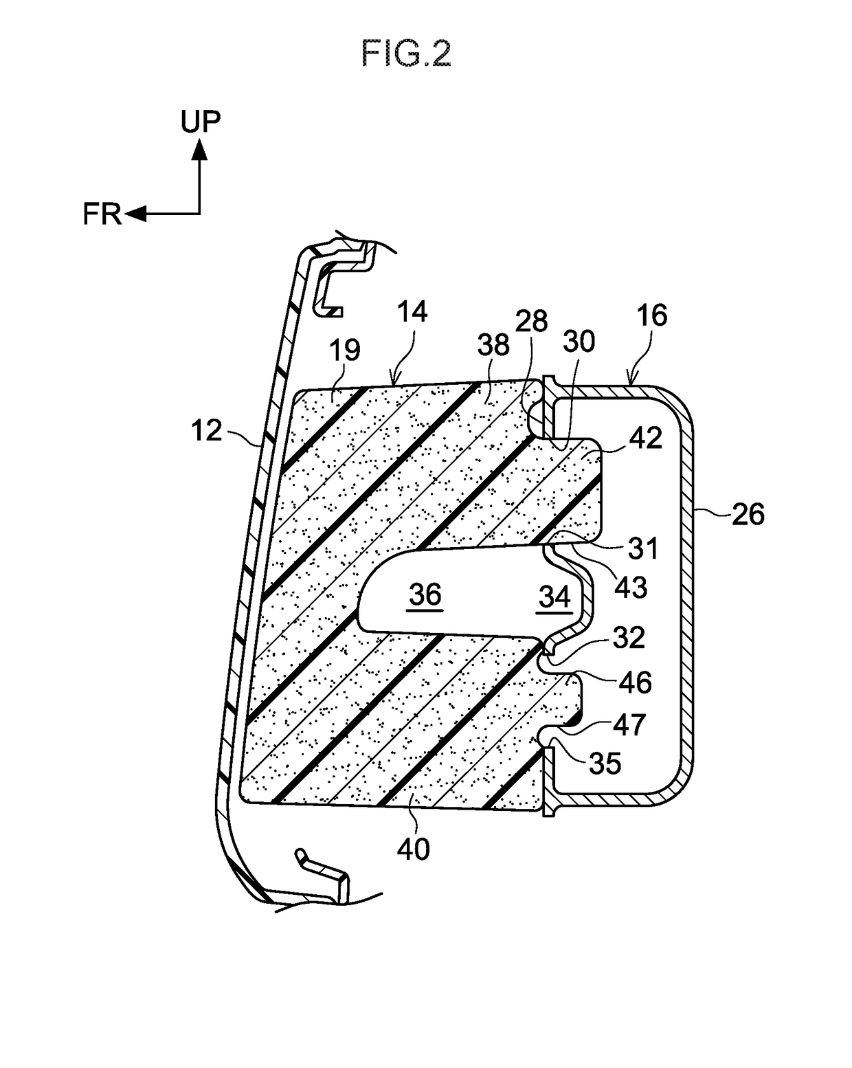
[0028]Explanation follows regarding a first exemplary embodiment of a bumper absorber attachment structure according to the present disclosure, with reference to FIG. 1 to FIG. 3. Note that in the drawings, the arrow FR indicates the vehicle front-rear direction front side, the arrow OUT indicates the vehicle width direction outside, and the arrow UP indicates the vehicle upper side, respectively.

[0029]As illustrated in FIG. 1, a front section of a vehicle 10 is configured including a front bumper cover 12, a front bumper absorber 14 serving as a bumper absorber, and front bumper reinforcement 16 serving as bumper reinforcement. The front bumper cover 12 is disposed at a foremost end of the vehicle 10, extends along the vehicle width direction, and is, as an example, configured as a styling face made of resin.

[0030]The front bumper reinforcement 16 is provided at the vehicle rear side of the front bumper cover 12. The front bumper reinforcement 16 is made of an aluminum alloy, forme...

second exemplary embodiment

[0053]Explanation follows regarding a second exemplary embodiment of a bumper absorber attachment structure according to the present disclosure, with reference to FIG. 4. Note that similar configuration portions to the first exemplary embodiment and so on previously described are appended with the same reference numerals, and explanation thereof is omitted.

[0054]The basic configuration of the bumper absorber attachment structure according to the second exemplary embodiment is similar to that of the first exemplary embodiment, with a feature that the second engagement holes 32 are not formed to front bumper reinforcement 50.

[0055]Namely, the front bumper reinforcement 50 is made of an aluminum alloy, formed in an elongated shape extending along the vehicle width direction, and has a cross-section profile orthogonal to the vehicle width direction formed in a substantially rectangular shape with its length direction along the vehicle vertical direction.

[0056]The first engagement holes ...


PUM


Abstract

There is provided a bumper absorber attachment structure including (1) bumper reinforcement, (2) a first engaged portion that is formed at a vehicle upper side of a side face at a vehicle front side of the bumper reinforcement, (3) a second engaged portion that is formed at a vehicle lower side of the side face at the vehicle front side of the bumper reinforcement, (4) a bumper absorber that includes a thinned portion, an upper leg, and a lower leg, (5) a first engagement portion that is formed at a vehicle rear side of the upper leg, and that engages with the first engaged portion, and (6) a second engagement portion that is formed at a vehicle rear side of the lower leg, and that engages with the second engaged portion in a case in which the bumper absorber is displaced toward the vehicle lower side in a collision.

Description

CROSS-REFERENCE TO RELATED APPLICATION[0001]This application claims priority under 35 USC 119 from Japanese Patent application No. 2015-042829 filed on Mar. 4, 2015, the disclosure of which is incorporated by reference herein.BACKGROUND[0002]Technical Field[0003]The present disclosure relates to a bumper absorber attachment structure.[0004]Background Art[0005]Japanese Patent Application Laid-Open (JP-A) No. 2007-145159 describes a structure of a bumper absorber. Specifically, a cross-section of the bumper absorber orthogonal to the vehicle width direction is formed in a substantially U-shape, by a thinned portion open toward the vehicle rear side, an upper leg provided at the vehicle upper side of the thinned portion, and a lower leg provided at the vehicle lower side of the thinned portion. An engagement protrusion is formed projecting out toward the vehicle rear at a vehicle rear side end portion of the upper leg. An engagement hole is formed piercing through in the plate thicknes...

Claims


Application Information

Patent Timeline
Patent Type & Authority Patents(United States)
IPC IPC(8): B60R19/34B60R19/18
CPCB60R19/34B60R19/18B60R2019/1873
Inventor TOMITA, YASUHIRO
Owner TOYOTA JIDOSHA KK
Why Eureka
Try Eureka