Vehicle and suspension arm

a technology for suspension arms and vehicles, applied in the field of vehicles and suspension arms, can solve the problems of deteriorating the support performance of the suspension arm in the normal traveling state of the vehicle, and the difficulty of designing the vehicle-body attachment portion, so as to reduce the collision load

Active Publication Date: 2020-11-24
MAZDA MOTOR CORP
View PDF14 Cites 0 Cited by
  • Summary
  • Abstract
  • Description
  • Claims
  • Application Information

AI Technical Summary

Benefits of technology

[0005]The present invention has been devised in view of the above-described matter, and an object of the present invention is to provide a vehicle and a suspension arm, which can reduce the collision load applied to the cabin by way of the front wheel as much as possible in the small overlap collision of the vehicle, without deteriorating the support performance of the suspension arm in the normal traveling state of the vehicle.
[0007]According to the present invention, when the load which is greater than the specified magnitude (i.e., the collision load) is inputted to the front wheel from the vehicle forward side in the small overlap collision, the suspension arm is bent at the fragile portion, whereby the front wheel is rotated rearwardly around the fragile portion of the suspension arm. Herein, since the fragile portion is provided at the portion of the suspension arm which is positioned near the vehicle-body attachment portion, a rotational radius of the front wheel can be large similarly to a case where the suspension arm (front wheel) is rotated around the vehicle-body attachment portion like the conventional example. Consequently, the front wheel can be displaced outwardly, in the vehicle width direction, relative to the cabin as much as possible, so that the collision load applied to the cabin by way of the front wheel can be reduced as much as possible. Meanwhile, differently from the case where the suspension arm is rotated around the vehicle-body attachment portion, it is unnecessary to consider the rotation of the suspension arm in the small overlap collision in designing the vehicle-body attachment portion. Accordingly, the support performance of the suspension arm is not deteriorated in the normal traveling state of the vehicle.
[0009]Herein, if the fragile portion is not provided, the suspension arm is generally bent at the maximum curvature portion when the collision load is applied to the front wheel from the vehicle forward side in the small overlap collision. In this case where the suspension arm is bent at the maximum curvature portion, since the maximum curvature portion is generally provided at a portion of the suspension arm which is located on a side of the front-wheel support portion relative to a portion where the fragile portion is provided, the front wheel tends to be easily displaced inwardly in the vehicle width direction (toward the cabin). According to this embodiment, since the fragile portion is positioned on the side of the vehicle-body attachment portion relative to the maximum curvature portion in the longitudinal direction of the suspension arm which is provided with the curve portion as described above, the suspension arm can be made to be bent at the fragile portion when the collision load is applied to the front wheel from the vehicle forward side. Accordingly, the collision load applied to the cabin by way of the front wheel can be reduced as much as possible.
[0013]According to this embodiment, the fragile portion can be constituted with a simple structure.

Problems solved by technology

Herein, it is actually difficult to design the vehicle-body attachment portion, considering these two.
Accordingly, in a case where the suspension devise is designed such that the suspension arm is easily rotated around the vehicle-body attachment portion, there is a problem that the support performance of the suspension arm in the normal traveling state of the vehicle may be deteriorated in a long term use.

Method used


Image

  • Vehicle and suspension arm
  • Vehicle and suspension arm
  • Vehicle and suspension arm

Examples


Embodiment Construction

[0024]Hereafter, an embodiment of the present invention will be described specifically referring to the drawings.

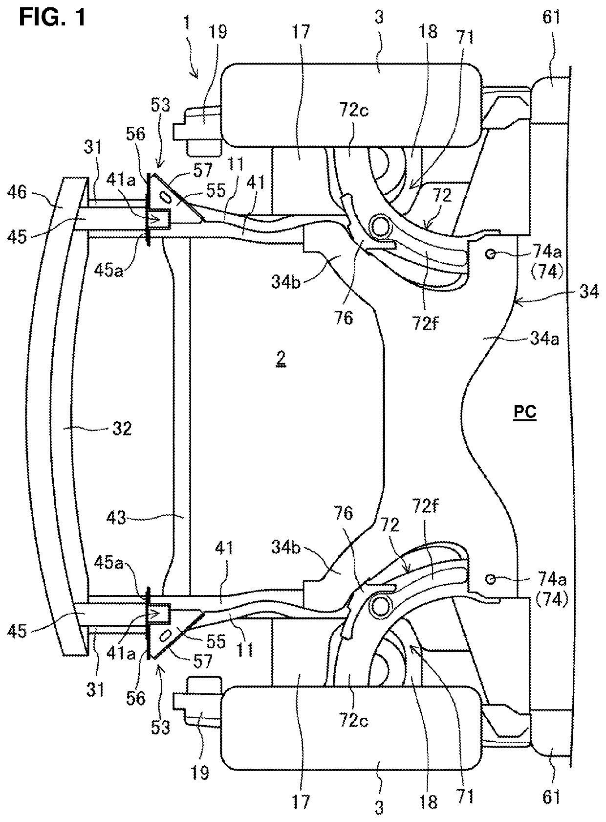
[0025]FIG. 1 shows a major part of a front portion of a vehicle 1 where a suspension device 71 for the vehicle according to the embodiment of the present invention is installed. An engine room 2 where a powertrain, not illustrated, which drives right-and-left front wheels 3 of the vehicle 1 are arranged is provided at the front portion of the vehicle 1. The powertrain comprises an engine and a transmission to which a torque (power) generated by the engine is inputted. The engine and the transmission are aligned in a vehicle width direction between a pair of right-and-left front side frames 11 which will be described later. A cabin PC is formed behind the engine room 2 where passengers are seated. Hereafter, respective forward (front), rearward (rear), leftward (left), rightward (right), upward (up), and downward (down) sides of the vehicle 1 will be referred to simply as ...


PUM


Abstract

A fragile portion is provided at a portion of a suspension arm which is positioned near a vehicle-body attachment portion. The fragile portion is configured such that when a load which is greater than a specified magnitude is inputted to a front wheel from a vehicle forward side, the suspension arm is bent at the fragile portion, whereby the front wheel is rotated rearwardly around the fragile portion.

Description

BACKGROUND OF THE INVENTION[0001]The present invention relates to a vehicle comprising a suspension arm which is provided with a front-wheel support portion supporting a front wheel of the vehicle at one end thereof and a vehicle-body attachment portion attached to a vehicle-body member of the vehicle at the other end thereof, the vehicle-body attachment portion being positioned on an inward side, in a vehicle width direction, of the front-wheel support portion, and the suspension arm itself.[0002]Conventionally, a vehicle frontal collision in which the vehicle collides with an obstacle at a position of the vehicle which is located on an outward side, in the vehicle width direction, of a front side frame is called a small overlap collision. In this small overlap collision, there is a case where the front wheel retreats and then hits against a vehicle body which is positioned in back of the front wheel. In this case, a collision load generated in this collision is possibly applied to...

Claims


Application Information

Patent Timeline
Patent Type & Authority Patents(United States)
IPC IPC(8): B60G7/00B62D21/15
CPCB62D21/152B60G7/001B60G2206/016B60G2206/8102B60G2206/122B60G2206/8201B60G7/00B60G2200/10
Inventor KANAMARU, DAISUKEKIDO, HIROTOISHIKAWA, YASUSHIKAWAMOTO, ATSUSHIUCHIBA, YUUKIKIMURA, HIROKISANO, SUSUMU
Owner MAZDA MOTOR CORP
Why Eureka
Try Eureka