
Power source system with multiple electrical outputs

a power source and output technology, applied in the field of systems for providing power sources, can solve the problems of difficult access to electrical equipment areas, affecting the safety of users,

Active Publication Date: 2017-08-15
JOHN FLUKE MFG CO INC
View PDF15 Cites 15 Cited by
  • Summary
  • Abstract
  • Description
  • Claims
  • Application Information

AI Technical Summary

Problems solved by technology

Some electrical equipment areas can be difficult to access.
Such panels can be large, sometimes requiring more than one person to open, and opening such panels can take a significant amount of time and energy.
Electrical equipment areas can also be dangerous, such as in the case of electrical equipment areas that contain high energy circuits.
However, the use of personal protective equipment can be slow and cumbersome, adding to the time and cost of entering electrical equipment areas.
Safety concerns may also necessitate shutting down some or all of the electrical equipment when people enter electrical equipment areas, resulting in loss of service by the electrical equipment while people are accessing the area.

Method used


Image

  • Power source system with multiple electrical outputs
  • Power source system with multiple electrical outputs
  • Power source system with multiple electrical outputs

Examples


Embodiment Construction

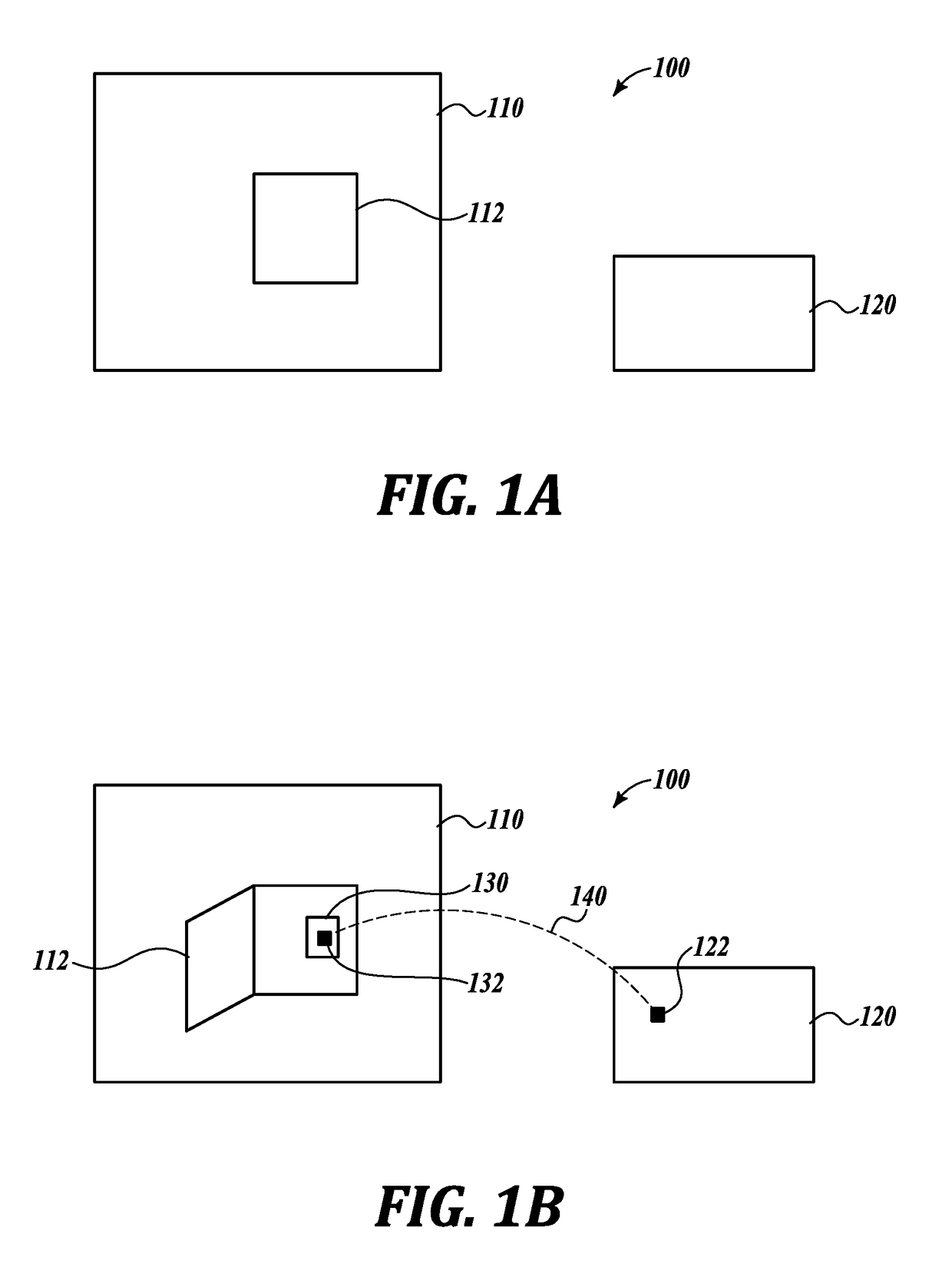
[0028]FIGS. 1A and 1B depict an example of a system 100 that includes an electrical equipment area 110 and a monitoring station 120. In some examples, the electrical equipment area 110 can be an enclosure, such as an electrical panel or a Faraday room or cage, a restricted area, such as a fenced-in electrical substation, or any other type of area that can contain or hold electrical equipment. Although not depicted in FIGS. 1A and 1B, the electrical equipment may include electrical components, such as electrical wires, transformers, capacitors, circuit breakers, switches, voltage regulators, and the like. The electrical equipment may also include non-electrical components that support electrical components, such as support structures, towers, fences, poles, conduits, and the like.

[0029]The monitoring station 120 may include a computing device, such as computer or a server, and can be used to monitor conditions within the electrical equipment area 110. The monitoring station 120 is lo...


PUM


Abstract

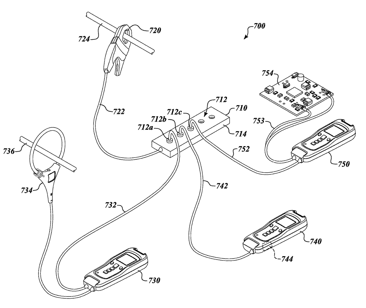
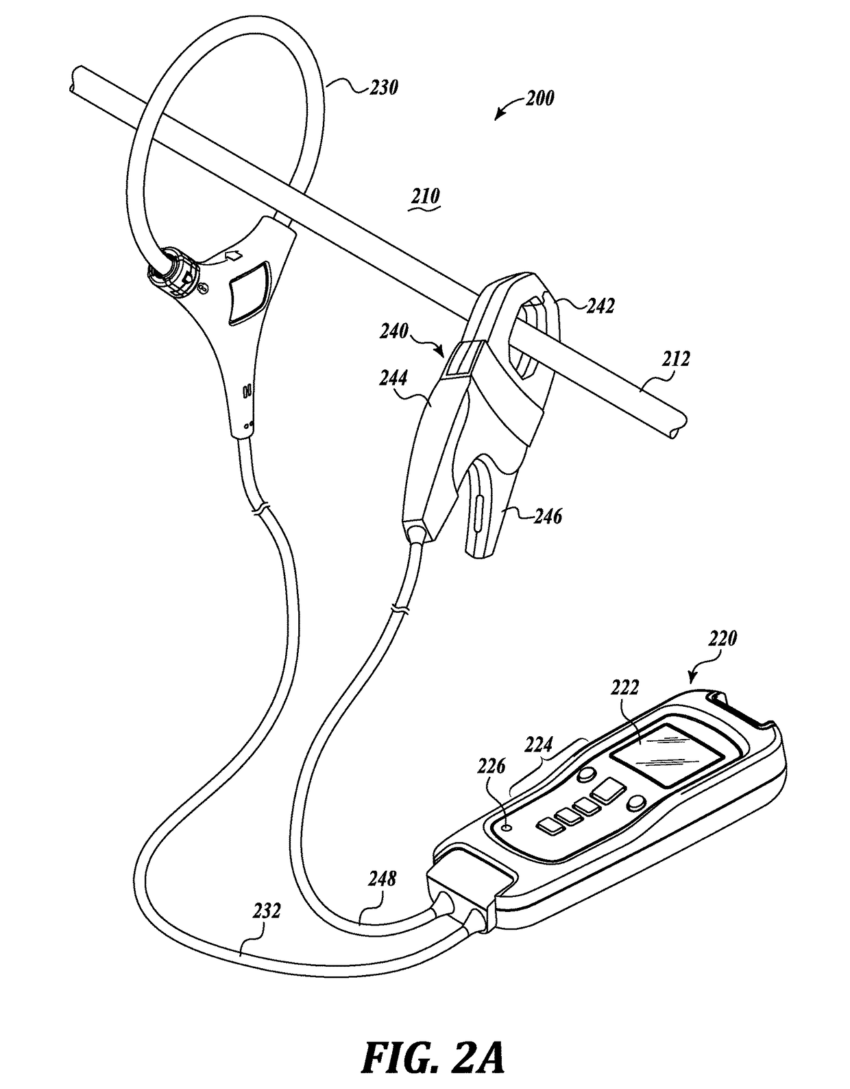
A system providing a power source includes an electrical input and multiple electrical outputs. The electrical input is couplable to a current clamp that selectively clamps around at least one electrical conductor. A transformer coupled to the electrical input receives an input electrical signal from the at least one electrical conductor and produces an output electrical signal that is electrically isolated from the input electrical signal. Conversion circuitry electrically converts the output electrical signal to a converted electrical signal that is usable to power multiple electrical devices. Distribution circuitry distributes the converted electrical signal to the multiple electrical outputs, wherein each electrical output is couplable to an electrical device to provide power to the electrical device.

Description

BACKGROUND[0001]Technical Field[0002]The present disclosure relates to systems for providing a power source for multiple electrical devices, such as testing devices, in an electrical equipment area.[0003]Description of the Related Art[0004]Various testing devices are used to measure parameters of electrical equipment areas. For example, sensors can detect electrical characteristics of the electrical equipment, such as voltage, current, resistance, and the like. Sensors can also detect environmental characteristics of the electrical equipment area or the surrounding area, such as temperature, pressure, humidity, and the like. Data obtained from the testing devices can be used to evaluate performance of the electrical equipment, potential dangers to the electrical equipment, needed adjustments or maintenance of the electrical equipment, and the like.[0005]Some electrical equipment areas can be difficult to access. For example, electrical equipment areas can be enclosed and accessible ...

Claims


Application Information

Patent Timeline
Patent Type & Authority Patents(United States)
IPC IPC(8): H02J5/00G01R15/14G01R19/25G01R15/18G01R1/22G01D11/00H02J1/08H02M7/04
CPCH02J5/005G01D11/00G01R1/22G01R15/14G01R15/186G01R19/2513H02J1/08H02M7/04H02J1/108H02J50/10G01R1/02
Inventor GILBERT, JOHN M.EPPERSON, DAVID L.RINGSRUD, PAUL A.
Owner JOHN FLUKE MFG CO INC
Learn More