
Medical, in particular surgical, sliding-shaft instrument

a technology of sliding shaft and sliding shaft, which is applied in the field of medical devices, can solve the problems of unintentional disassembly of instruments, awkward handling of slider and handle arm components, and previously known design and mechanism of releasable connection of shaft elements,

Inactive Publication Date: 2017-08-08
WALDEMAR LINK GMBH & CO
View PDF9 Cites 0 Cited by
  • Summary
  • Abstract
  • Description
  • Claims
  • Application Information

AI Technical Summary

Benefits of technology

This patent text describes a design for a handle arm that has a second slot and a third leg. The second slot runs parallel to the first slot and is connected to the material of the second handle arm. This design creates a first leg that is resilient and has a uniform material thickness. The third leg is rigid and will not yield or deform easily. This ensures that the handle arm can withstand excessive force and remains rigid as a stop.

Problems solved by technology

The slider and shaft element are typically connected to one another by a guide, which does not allow separation of these two elements over a wide range of possible positions of the slider and shaft element relative to one another, and which guides the longitudinal movement of the slider and securing it with respect to additional relative movements of the slider relative to the shaft element.
It has now been found that the previously known designs and mechanisms for the releasable connection of the shaft element, slider and handle arm components are awkward to handle, which relates to operation, on the one hand, and the cleaning and sterilization, on the other hand.
First, in the case of the locking switches arranged in the region of the handle arms, there is the risk of unintentional operation during use, in particular when the locking switches are designed as sliding switches, for example, when an additional pressure must be applied by the thumb on a hand operating the sliding-shaft instrument in an upper section of the instrument on the proximal end of the shaft element and / or in the upper region of a handle arm.
If a movement of the slider in the direction of the proximal end is then carried out and it goes beyond the end position, in which the slider and shaft element are still connected, the instrument may then be dismantled unintentionally during use with corresponding negative consequences and impairment of the sequence of the medical procedure in which the sliding-shaft instrument is used.
Furthermore, all such locking switches, bolt slides or turn bolts offer additional small interspaces, into which impurities can penetrate together with blood, tissue fragments, bone chips or the like during the medical procedure and use of the sliding-shaft instrument, which interspaces are naturally difficult to access and can therefore be cleaned only with substantial effort, and often even only inadequately, and then sterilized.

Method used


Image

  • Medical, in particular surgical, sliding-shaft instrument
  • Medical, in particular surgical, sliding-shaft instrument
  • Medical, in particular surgical, sliding-shaft instrument

Examples


Embodiment Construction

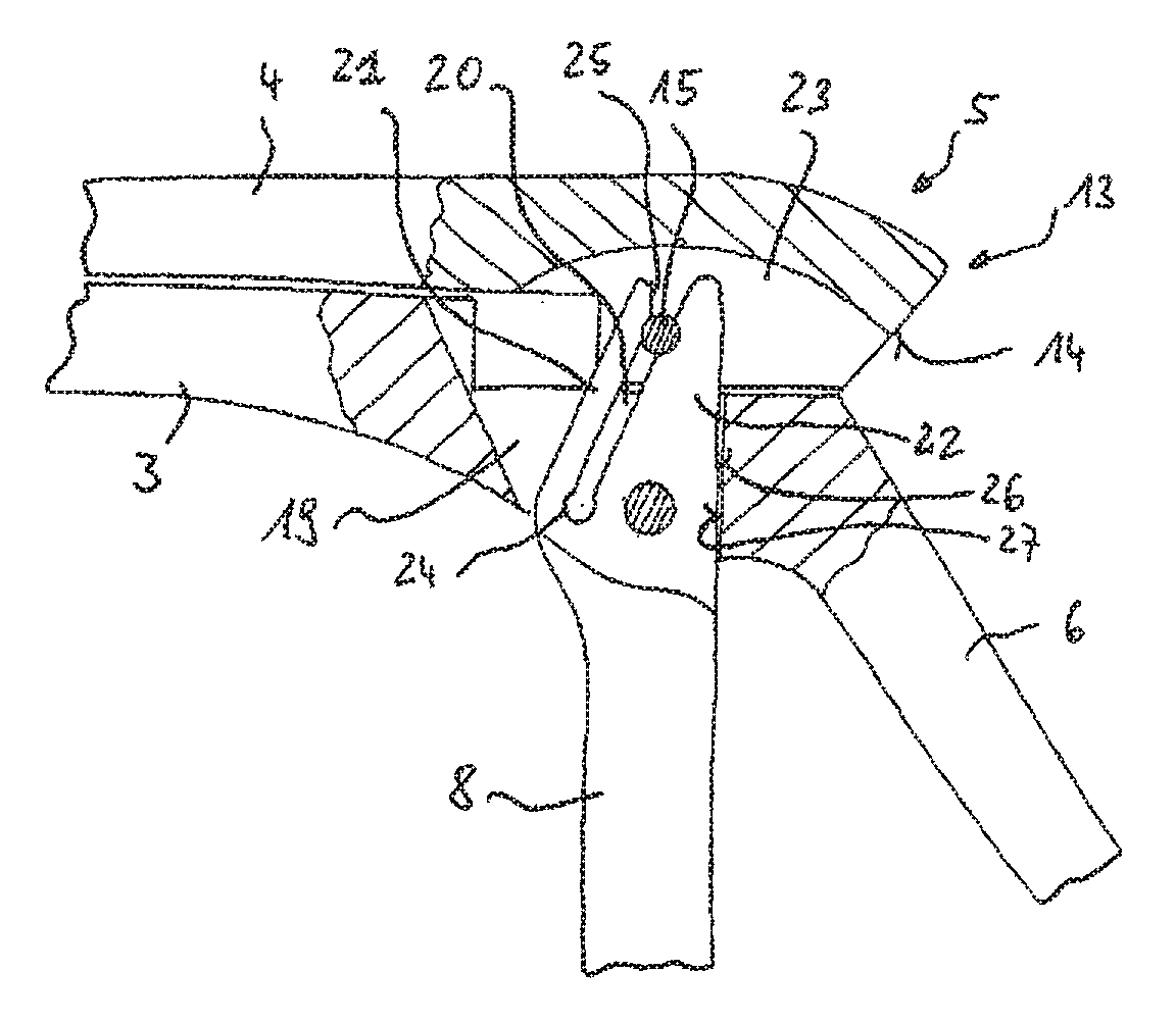
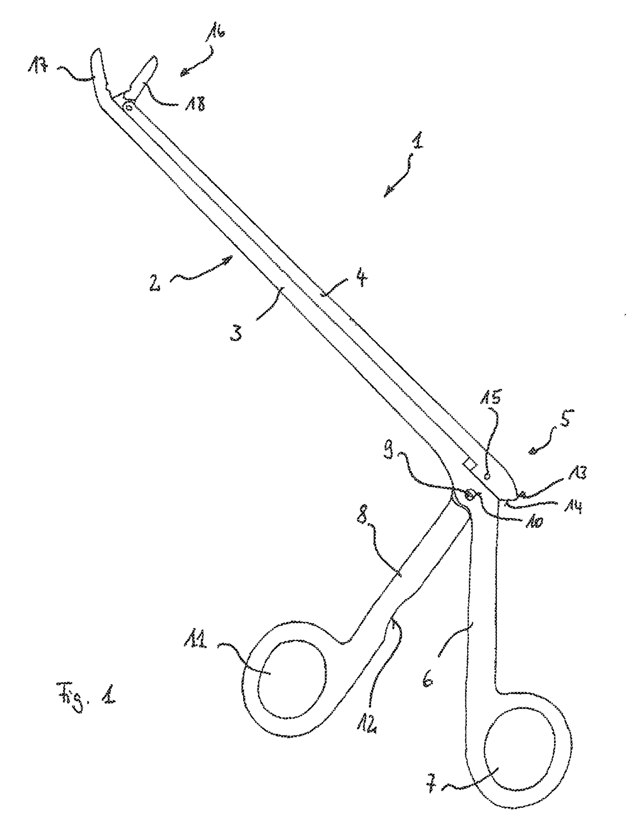
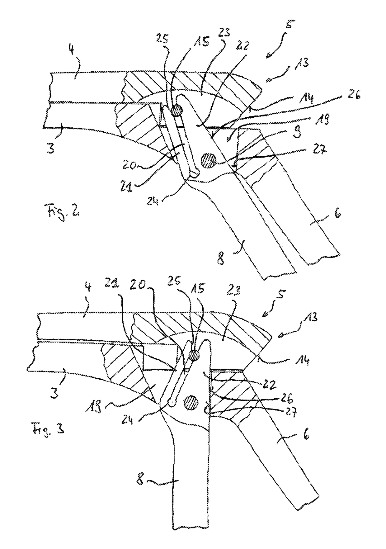
[0012]According to the invention, the object is achieved by designing a medical, in particular surgical, sliding-shaft instrument of the aforementioned type, so that a first leg of the legs bordering the first slot is formed as a resilient tongue that is movable outward away from the second one of the legs, across its direction of longitudinal extent, wherein the second handle arm is positioned in the proximal end position in such a way that the cross pin lies in the first slot and is at least partially covered and retained by the first leg, formed as a resilient tongue, in a release direction which points essentially perpendicular to the axial line of the shaft element in the direction of the slider, which cross pin is releasable by applying a releasing force in the release direction and displacement of the end of the first leg, directed against the spring force of the resilient tongue, and wherein a lug is arranged on the proximal end of the slider, protruding in the proximal end ...


PUM


Abstract

A medical sliding-shaft instrument having a first handle arm, a second handle arm pivotably mounted to the first handle arm, a shaft connected to the first handle arm and a slider coupleable to the second handle arm and axially displaceable on the shaft. The slider is removable from the shaft and is guided along a sliding path. A cross-pin couples the second handle arm to the slider and is received in a slot defined by first and second legs of the second handle arm. The first leg is a resilient tongue moveable transversely to a longitudinal axis of the first leg and outwardly away from the second leg. The second handle arm is positioned so that the cross pin lies in the slot. The cross pin is covered and held back by the first leg and is released by applying a force and displacing the end of the first leg.

Description

TECHNICAL FIELD[0001]The present invention relates to a medical, in particular surgical, sliding-shaft instrument having a first handle arm and a second handle arm pivotably mounted with respect to the first handle arm, having a shaft element connected to the first handle arm and a slider that is axially displaceable on the shaft element and can be coupled to the second handle arm, wherein the slider can be removed from the shaft element in a retracted proximal end position of its sliding path and in the proximal end position of additional regions of its sliding path displaced in the direction of a pushed-forward distal end position, is guided inseparably on the shaft element, and wherein a cross in arranged on the slider is accommodated in a first slot of the first handle arm, which is open at the end and is bordered by two legs for coupling the second handle arm to the slider.PRIOR ART[0002]Such sliding-shaft instruments are characterized in that they have a typically elongated sh...

Claims


Application Information

Patent Timeline
Patent Type & Authority Patents(United States)
IPC IPC(8): A61B17/29A61B17/16A61B17/00A61B90/00
CPCA61B17/2909A61B17/1608A61B17/00234A61B17/29A61B2017/292A61B2017/2902A61B2017/2916A61B2017/2917A61B2017/2924A61B2017/2944A61B2017/2947A61B2090/0813
Inventor DMUSCHEWSKY, KLAUS
Owner WALDEMAR LINK GMBH & CO
Learn More