Image capturing apparatus, image capturing system, and control method for the image capturing apparatus

a technology of image capturing apparatus and image sensor, which is applied in the direction of television system, radio frequency control device, instruments, etc., can solve the problems of high processing load, inability to correct in real-time, and increase the scale of image processing lsi, so as to suppress the reduction in quality of correction processing and reduce the amount of ob pixel region data

Inactive Publication Date: 2017-08-01
CANON KK
View PDF21 Cites 5 Cited by
  • Summary
  • Abstract
  • Description
  • Claims
  • Application Information

AI Technical Summary

Benefits of technology

[0011]The present invention has been achieved in light of such circumstances, and provides a technique for, in the case where correction processing that uses OB pixel region data is performed after image data recording, reducing the amount of OB pixel region data that is recorded while also suppressing a reduction in quality in correction processing.

Problems solved by technology

In recent years, there have been cases where CMOS image sensors used as image sensors in image capturing apparatuses have generated various types of noise due to their structure.
However, since the amount of information per frame is large in a video signal that has a high pixel count, correcting it in real-time involves a high processing load.
This leads to the problems of an increase in the scale of the image processing LSI and an increase in power consumption.
For this reason, the RAW data has a large size, and the amount of capacity consumed in the recording medium increases.

Method used


Image

  • Image capturing apparatus, image capturing system, and control method for the image capturing apparatus
  • Image capturing apparatus, image capturing system, and control method for the image capturing apparatus
  • Image capturing apparatus, image capturing system, and control method for the image capturing apparatus

Examples


first embodiment

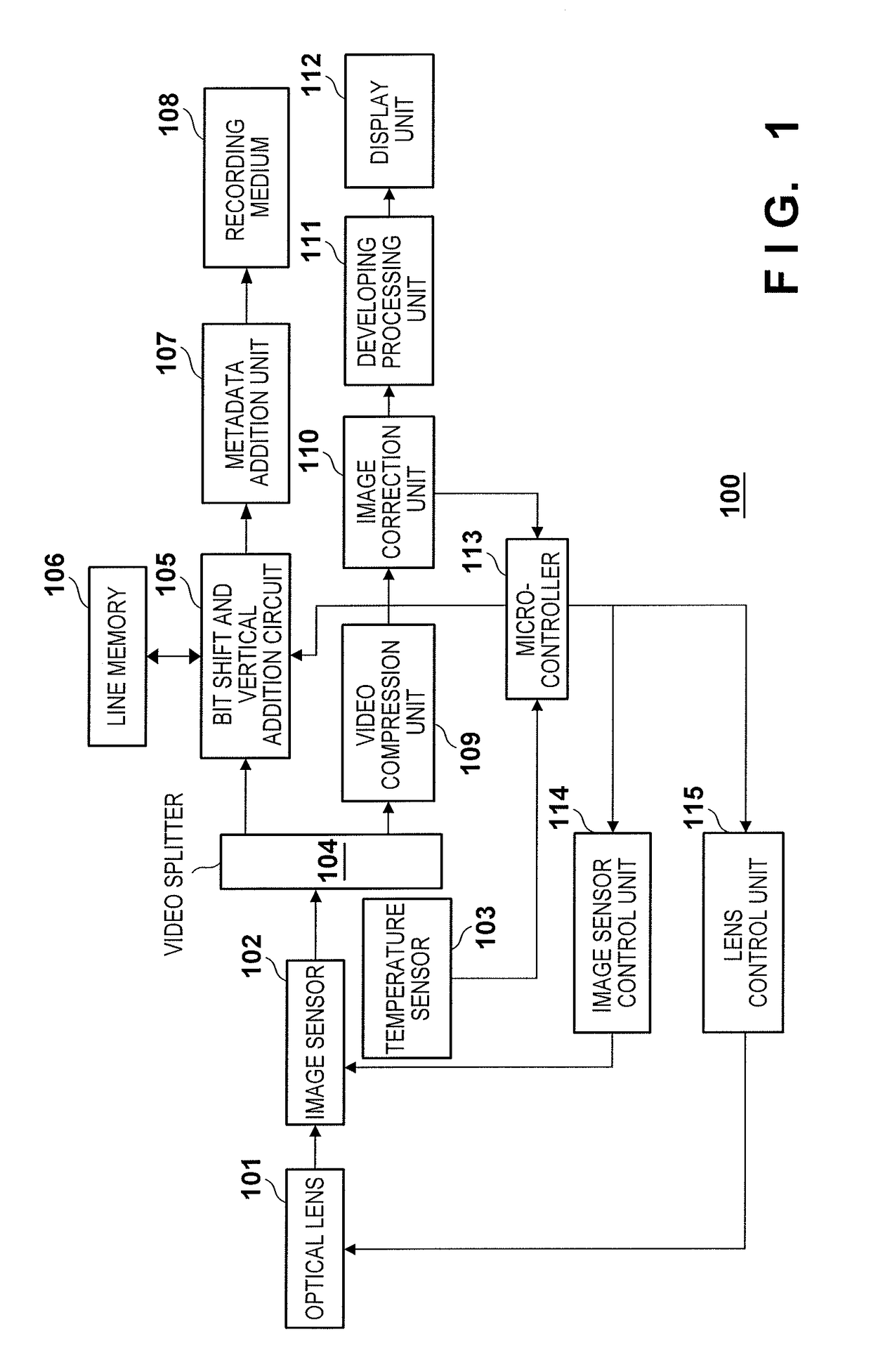
[0025]FIG. 1 is a diagram showing function blocks of an image capturing apparatus 100 according to a first embodiment. In FIG. 1, an optical lens 101 picks up subject light. The optical lens 101 typically has a focus mechanism for focusing, a diaphragm mechanism for adjusting the light quantity and depth of field, and a zoom mechanism for changing the focal length. Note that if the lens is a single-focus lens, the zoom mechanism is not provided. Also, if the lens is a pan-focus lens, the focus is only on one point at infinity, and the focus mechanism is not provided. In order to reduce the cost of the lens, there are cases where the diaphragm position is set to one position, and an ND filter for adjusting the light quantity is used as a substitute. In the present embodiment, any optical lens may be used as the optical lens 101 as long as it transmits light to form an image on an image sensor 102.

[0026]The image sensor 102 receives incident light from the optical lens 101, converts i...

second embodiment

[0060]A configuration in which OB pixel region data is deleted in order to greatly reduce the data amount of the OB pixel region will be described in a second embodiment. Also, in the configuration described below, in the case where the OB pixel region has been compressed in multiple frames obtained by performing image capture multiple times consecutively, the OB pixel region is not compressed in the frame obtained in the next instance of image capture regardless of the degree of change in the correction target component. In the present embodiment, the basic configuration of the image capturing apparatus 100 is similar to that in the first embodiment (see FIG. 1).

[0061]FIG. 5 is a flowchart showing the flow of OB pixel region compression processing according to the second embodiment. Steps in this flowchart that are for performing processing the same as or similar to steps in FIG. 4 have been given the same reference signs, and these steps will not be described.

[0062]In step S501, t...


PUM

PropertyMeasurementUnit
thresholdaaaaaaaaaa
power consumptionaaaaaaaaaa
image processingaaaaaaaaaa

Abstract

An image capturing apparatus comprises an image capturing unit that includes an image sensor that has an effective pixel region and a reference pixel region which outputs a reference signal for correcting an output signal of the effective pixel region. In a case where a predetermined condition is satisfied, a reduction unit reduces a data amount of reference pixel region data that corresponds to the reference pixel region in an image data obtained by the image capturing unit. A recording unit records the image data after the processing performed by the reduction unit.

Description

BACKGROUND OF THE INVENTION[0001]Field of the Invention[0002]The present invention relates to an image capturing apparatus, image capturing system, and a control method for the image capturing apparatus.[0003]Description of the Related Art[0004]The number of pixels that can be recorded in image capturing apparatuses such as digital video cameras has increased in recent years. This is closely related to the standards of monitors for displaying video recorded by image capturing apparatuses. Specifically, there has been a transition from the so-called SD (Standard Definition) standard to the so-called HD (High Definition) standard, and a transition to monitors having an even higher resolution is planned for the future.[0005]The HD resolution is mainly 1920 pixels in the horizontal direction by 1080 pixels in the vertical direction (referred to hereinafter as 1920×1080 pixels), and the resolution of so-called 4K2K monitors thought to be the next generation is 3840×2160 pixels, which is ...

Claims


Application Information

Patent Timeline
Patent Type & Authority Patents(United States)
IPC IPC(8): H04N5/335H04N5/911G11B20/00G11B20/22G11B20/24H04N5/365H04N5/77H01L27/146
CPCG11B20/00007G11B20/22G11B20/24H04N5/365H04N5/3655H04N5/772H04N5/911G11B2020/00072H04N25/67H04N25/673G02B13/00G06T1/00H01L27/14G06V20/10G06V10/20
Inventor KOBUSE, TAKENORI
Owner CANON KK
Why Eureka
Try Eureka