Eureka AIR delivers breakthrough ideas for toughest innovation challenges, trusted by R&D personnel around the world.

Centrifuge drive head for releasably connecting a driving system to a rotor of a centrifuge, a set and a centrifuge comprising the drive head

a centrifuge and drive head technology, applied in the direction of centrifuges, rigid shaft couplings, couplings, etc., can solve the problems of system reaches its limits, rotor jamming, and dynamic instability, and achieve the effect of convenient installation, high strength and improved stability

Active Publication Date: 2017-08-01
THERMO ELECTRONICS LED GMBH
View PDF24 Cites 9 Cited by
  • Summary
  • Abstract
  • Description
  • Claims
  • Application Information

AI Technical Summary

Benefits of technology

[0008]It is thus an object of the present invention to overcome the disadvantages of the prior art mentioned above. More particularly, it is an object of the present invention to provide a centrifuge drive head comprising a self-locking and rapidly releasable coupling, which drive head ensures that the rotor is fixed securely over a wide range of rotational speeds ranging from the idle state of the rotor up to 30,000 rpm (revolutions per minute) without becoming jammed. Furthermore, the present invention is to be universally applicable, that is to say, it should function for fast-rotating light rotors as well as for slow-rotating heavy rotors. Moreover, the present invention should be able to absorb high axial forces that might result from buoyancy.

Problems solved by technology

However, the unlocking mechanism disclosed therein is difficulty available for many conventional designs of rotor, and the rotor is not guided sufficiently without play, which might result in dynamic instability at relatively high loads and rotational speeds.
However, it is only suitable for specific types of rotor that do not generate any forces (for example, buoyancy forces) contrary to the coupling direction.
However, this system reaches its limits when higher buoyancy forces and / or very high rotational speeds occur.
Furthermore, the rotor gets jammed as a result of the high centrifugal forces at very high rotational speeds and the coupling cannot always be easily detached.

Method used


Image

  • Centrifuge drive head for releasably connecting a driving system to a rotor of a centrifuge, a set and a centrifuge comprising the drive head
  • Centrifuge drive head for releasably connecting a driving system to a rotor of a centrifuge, a set and a centrifuge comprising the drive head
  • Centrifuge drive head for releasably connecting a driving system to a rotor of a centrifuge, a set and a centrifuge comprising the drive head

Examples


Embodiment Construction

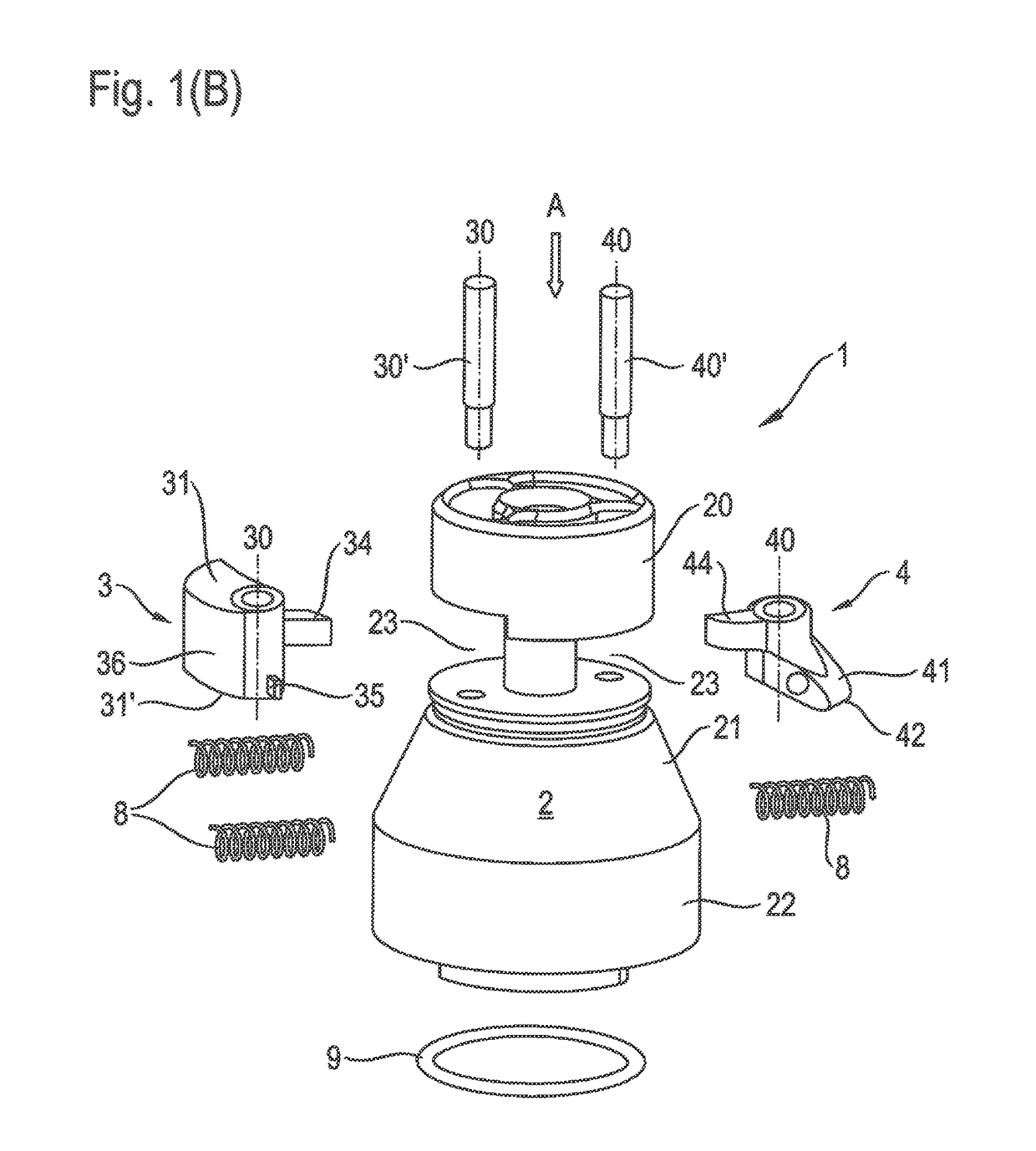
[0040]FIG. 1(A) is a perspective view of a centrifuge drive head 1 according to one embodiment of the present invention; FIG. 1(B) shows the same drive head in the form of an exploded view. The drive head 1 comprises a base body 2 comprising a substantially cylindrical top region 20 and a lower region 21 in the form of a truncated cone. This portion is adjoined by a bottom cylindrical region 22. Between the top region 20 and the lower region 21 of the drive head there are located two coupling elements 3 and 4 that are in the form of pivotal wedges.

[0041]According to one aspect of the present invention, the two coupling elements 3 and 4 differ from each other. In the example shown, they differ in terms of their geometric shape and material. The first coupling element 3 is larger and more massive than the second coupling element 4. The coupling element 3 is made of steel in the example shown while the coupling element 4 is made of titanium. Both steel and titanium have very high stren...


PUM


Abstract

A centrifuge drive head for releasably connecting a driving system to a rotor of a centrifuge. The centrifuge drive head comprises a base body mounted for rotation about an axis of rotation (R) and at least a first and a second coupling element, mounted on the base body for swinging outwardly about a swivel axis. The first and second coupling elements differ from each other in at least one of outer shape, mass, material and / or mounting height on the base body.

Description

CROSS-REFERENCE TO RELATED APPLICATIONS[0001]The present application claims priority under 35 U.S.C. §119 of German Patent Application No. 10 2012 011 531.8, filed Jun. 8, 2012, the disclosure of which is hereby incorporated herein by reference in its entirety.FIELD OF THE INVENTION[0002]The present invention relates to centrifuges that hold sample containers and are used for separating the constituents of the samples contained therein at a high rotational speed of a centrifuge rotor. More particularly, the present invention relates to a centrifuge drive head for releasably connecting a driving system to a rotor of a centrifuge, which drive head comprises a base body and at least two coupling elements capable of swinging outwardly from the same. The present invention further relates to a set for a centrifuge, which set consists of a centrifuge drive head and at least one hub for a rotor. Finally, the present invention also relates to a centrifuge comprising the drive head or the set...

Claims


Application Information

Patent Timeline
Patent Type & Authority Patents(United States)
IPC IPC(8): B04B9/08B04B9/00F16D1/116
CPCB04B9/00B04B9/08F16D1/116B04B2009/085
Inventor BALLHAUSE, NORMANHENNE, SEBASTIAN
Owner THERMO ELECTRONICS LED GMBH
Why Eureka
Eureka Blog
Learn More