Connection joint for attaching an airfoil blade to a helicopter's bearingless main rotor

a technology of bearingless rotor and connection joint, which is applied in the direction of mechanical equipment, machines/engines, transportation and packaging, etc., can solve the problems of high technical and mechanical demands of separable or releasable junctions, subject to high loads in these various directions, etc., to improve lead lag kinematics, improve the folding of airfoil blades, and increase the distance

Active Publication Date: 2017-07-25
AIRBUS HELICOPTERS DEUT GMBH
View PDF21 Cites 2 Cited by
  • Summary
  • Abstract
  • Description
  • Claims
  • Application Information

AI Technical Summary

Benefits of technology

[0022]Particularly according to the invention, the distances of each of the two openings from the pitch axis of the airfoil blade can be different, to optimize the folding of the airfoil blade and to improve the lead lag kinematics by increasing the distances. Particularly according to the invention, the airfoil blade includes a main opening and a supporting opening that are both arranged lying perpendicular to the lead-lag pivoting plane of the rotor blade. In this context, the lead-lag pivoting plane essentially corresponds to the rotation plane of the rotor blade. The inventive airfoil blade achieves the advantage that the lead-lag pivoting stiffness at the separable or releasable junction is substantially increased by the maximized distance between said one main opening and said supporting opening. Said main opening and said supporting opening configuration allow an integration at a suitable location of the inventive airfoil blade more easily than the arrangement of a plurality of equally charged openings provided with any of the prior art arrangements. Said main opening is located nearby the maximum thickness of the profile of the blade attachment. The invention allows a reduced total structural height at an extended width of the profile of the airfoil blade without detracting from the mechanical strength of the junction.
[0023]Consequently the inventive airfoil blade achieves to configure the control cuff with a reduced profile height at the root end of said airfoil blade and therewith provide an improved overall aerodynamic configuration without any perturbing slits in the exterior profile and / or any projecting bolts of the control cuff and / or at the root end of said airfoil blade. The junction arrangement of the invention with the large distance between said main opening and said supporting opening also takes up and transmits the lead-lag moments so as to achieve a transfer from the airfoil blade into the lead-lag stiff control cuff, allowing improved efficiency of the lead-lag dampers arranged next to the control cuff / rotor head junction subsequently allowing less complex lead-lag dampers with reduced weight, smaller size and lower costs at fabrication and / or for maintenance during operation.
[0024]The inventive airfoil blade is provided with holes for attaching the main and supporting openings. The inventive airfoil blade, the flexbeam and the control cuff are separately fabricated. The airfoil blade is attached to the flexbeam / cuff unit by the main bolt and the supporting bolt. With the inventive airfoil blade it is possible to pivot the lift-generating airfoil blade relative to the flexbeam and the control cuff in the lead-lag plane for the purpose of folding the rotor blade into a folded configuration, in a very quick and simple manner. Namely, it is simply possible to remove a single one of the fastening bolts from the inventive airfoil blade, in order to allow the airfoil blade to be pivoted about the other remaining bolt to achieve the desired rotor blade folding. With the inventive airfoil blade an easy folding in both directions, forward and rearward is possible.

Problems solved by technology

During operation, the rotor blades are deflected in various directions and are thereby subjected to high loads in these various directions.
The separable or releasable junction is subject to high technical and mechanical demands, because it must reliably carry and transmit the substantially high centrifugal forces resulting during rotation of the rotor blade and all bending moments from flapping and lead lag movements of the rotor blade.

Method used


Image

  • Connection joint for attaching an airfoil blade to a helicopter's bearingless main rotor
  • Connection joint for attaching an airfoil blade to a helicopter's bearingless main rotor
  • Connection joint for attaching an airfoil blade to a helicopter's bearingless main rotor

Examples


Embodiment Construction

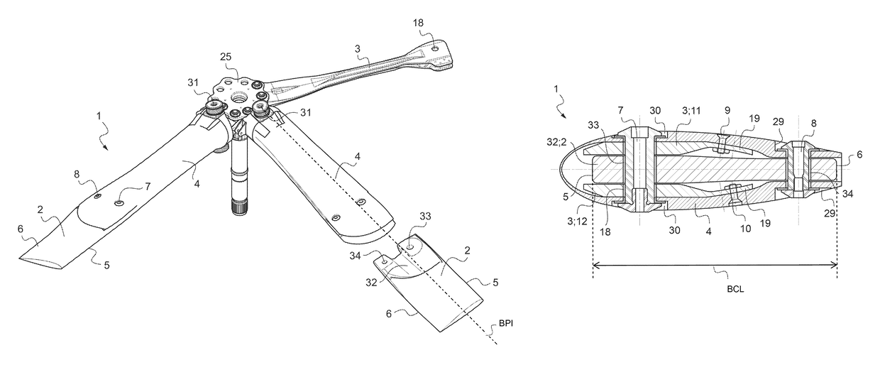
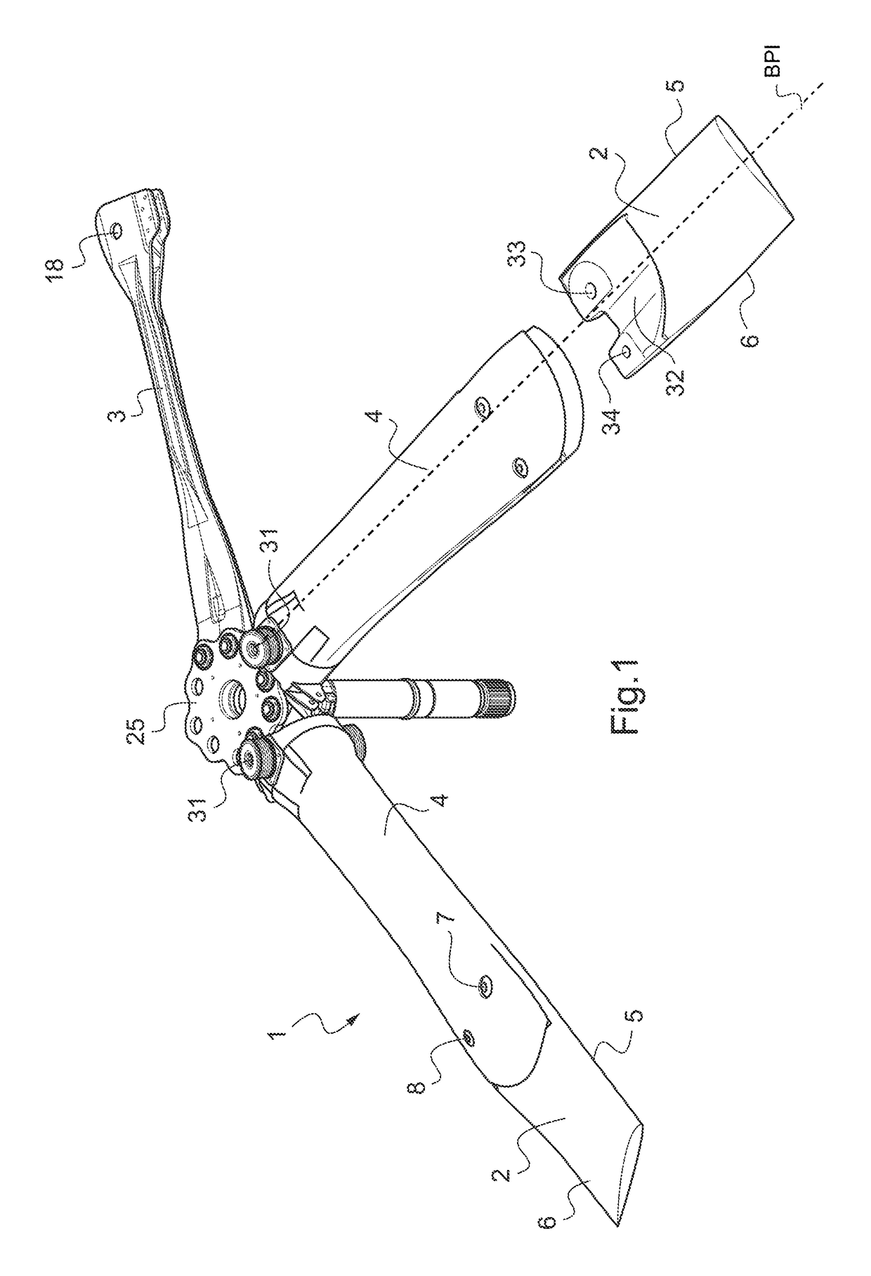
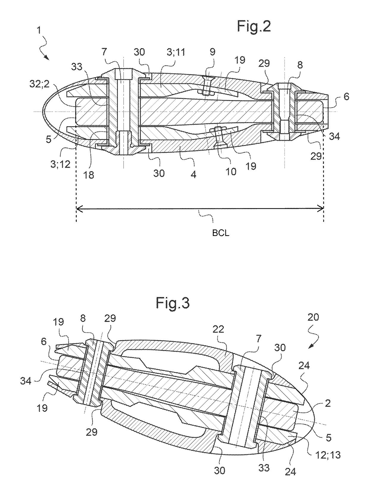
[0035]According to FIG. 1 a blade attachment 1 for a bearingless rotor of a helicopter (not shown) comprises an airfoil blade 2, a flexbeam 3 and a torsion stiff control cuff or torque tube 4 enclosing the flexbeam 3. The airfoil blade 2 is mounted by means of the flexbeam 3 and the control cuff 4 to a rotor head 25. Lead lag dampers 31 are arranged on the control cuffs 4 next to the rotor head 25.

[0036]The flexbeam 3 consists of a fiber-reinforced composite material. The root end of the flexbeam 3 is secured to the rotor head 25 of the helicopter (not shown). In operation each of the airfoil blades 2 rotate about an essentially vertical rotor head axis, whereby the airfoil blades 2 rotate with their lengthwise central axis in a rotor blade plane. This rotor blade plane substantially corresponds to the lead-lag pivoting or oscillating plane of the airfoil blades 2 of the bearingless rotor of the helicopter.

[0037]Each airfoil blade 2 has a leading edge 5 and a rear edge 6, a tip end ...


PUM


Abstract

An airfoil blade (2) of a bearingless rotor of a helicopter. Said airfoil blade (2) has a pitch axis from a tip end to a root end and said root end is provided with junction means for a separable junction arrangement of said airfoil blade (2) with a flexbeam head (13), and a control cuff (4, 22). Said junction arrangement is mechanical with removable fasteners respectively removable connecting said root end of said airfoil blade (2) to said control cuff (4, 22) and said flexbeam head (13). Said root end comprises at least two openings (7, 8) being asymmetric with regard to said pitch axis.

Description

CROSS-REFERENCE TO RELATED APPLICATIONS[0001]This application claims priority to European patent application No. 12 400012.6 filed Apr. 18, 2012, the disclosure of which is incorporated in its entirety by reference herein.BACKGROUND OF THE INVENTION[0002](1) Field of the Invention[0003]The invention relates to an airfoil blade of a bearingless rotor of a helicopter with the features of claim 1.[0004](2) Description of Related Art[0005]During operation, the rotor blades are deflected in various directions and are thereby subjected to high loads in these various directions. The rotor blades must be designed to withstand these high loads while still providing the required flexibility or articulation to allow the blades to carry out flapping, lead-lag oscillating, and pitch angle variation movements.[0006]Typically, a rotor blade of a bearingless rotor includes a structural element known as a flexbeam at the inner end of the blade connected to the rotor head. The flexbeam supports and t...

Claims


Application Information

Patent Timeline
Patent Type & Authority Patents(United States)
IPC IPC(8): F01D5/30B64C27/50B64C27/33B64C11/04B64C27/54B64C27/04B64C27/00
CPCF01D5/30B64C11/04B64C27/00B64C27/04B64C27/33B64C27/54B64C27/50
Inventor KUNTZE-FECHNER, GERALDBAUER, MARKUSORTNER, MARTIN
Owner AIRBUS HELICOPTERS DEUT GMBH
Why Eureka
Try Eureka